Getting Started with the 575 Curve Tracer
Setup and adjust the step-zero on the 575 curve tracer:
Tek 575
This semiconductor curve tracer displays the V-I (voltage vs current)
graph for semiconductor devices typically BJTs and FETs. For BJT, the base current is stepped.
For FETs the voltage is stepped.
- First, make sure that the Vertical and Horizontal
displays are zeroed: Hold the calibration switch for each one at
zero, and position the dot so it lies in the lower left corner of
the graticule for NPN devices, and in the upper right corner of
the graticule for PNP devices. This is best done with no
transistor under test [TUT] connected, and with the PEAK VOLTS
pot turned fully CCW.
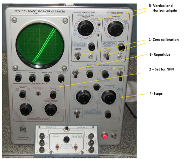
- Next, insert, for this example, an NPN device into the test socket, and set the polarity for NPN (2 places).
- Set the Vertical gain for 0.5mA/DIV, and the Horizontal
gain for 2V/DIV. Set the base current for 0.005 mA/STEP, set the
switch to "Repetitive" and turn the STEP ZERO control fully CW.
- Adjust the STEPS/FAMILY pot fully CCW, to 4
STEPS/FAMILY. You will actually see FIVE steps, the IB = 0 step,
and then the 4 steps corresponding to IB = .005 mA, .010 mA, .015
mA, and .020 mA.
- Once you have verified that there are five steps, now increase
the base current step selector to 0.01 mA/STEP. The upper steps
will disappear but it will be easier to view the 0th step.
- Push up the ZERO CURRENT switch and note where the 0th step
falls. Release the switch and adjust the STEP ZERO pot CCW until
the 0th step just moves down to the bottom line on the graticule
[IC=0, IB=0]. DO NOT TURN THE KNOB ANY FURTHER!. If you
continue to turn the knob, the 0th step trace will not go any
lower, but the 1st, 2nd, 3rd, 4th traces etc will move downward
and thus screw up the calibration. You may want to alternate
pushing up and releasing the ZERO CURRENT switch while you turn
the step zero knob.
- You should not have to repeat this calibration unless you use a
PNP transistor or someone else comes along and decides to do this
adjustment improperly!
- When you view the curves for JFET's on this curve tracer, be sure
to connect the 1000 ohm resistor across the base emitter
terminals to convert base mA to gate volts. Then, when you do
the calibration procedure above, just be sure to set the switch
to ZERO VOLTS during the calibration procedure.