6.111 Lab #3
V4.0 - (24bit RGB) 2018
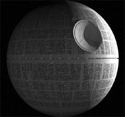
Goal: Implement a simple Pong like game with images on a VGA monitor with sound. In place of a puck, an image
of a Death Star from Stars Wars will be used. (Death Star from F2017 Project by Nicholas Waltman/Mike Wang.)
Useful links
This lab can be implemented on a Nexys 4 FPGA board. (Contact instructor)
Checkoff List
Please be ready with the following when checking off Lab #3:
- Set the labkit's switches to 0 (i.e., zero puck (Death Star) velocity) and
demonstrate your game in its reset state.
- Demonstrate the paddle moving along the left edge of the screen
in response to pushing the UP and DOWN buttons.
- Enter a small velocity in switch[7:4] and demonstrate the puck (Death Star)
moving and bouncing off the top, right and bottom of the screen.
- Implement and demostrate alpha blending.
- Demonstrate the puck (Death Star) bouncing off the paddle, and how your game
halts when the puck (Death Star) reaches the left edge of the screen.
- Demonstrate that your game can be restarted after halting by
pressing the ENTER button.
- Add one of the following
- flashing puck (Death Star) as puck (Death Star) hits the wall or paddle
- a two player version
- switchable paddle (left wall or right wall)
- ps2 mouse controlled paddle ps2_mouse.v
- a two player version
- disappearing puck (Death Star) as puck (Death Star) approaches paddle
- display total elapsed playing time on labkit hex display
display_16hex.v
- sound as the puck (Death Star) hits the wall or paddle
Grading: Items 1-6: 4 points; Items 1-7: 6 points.
During checkoff you may be asked to discuss one or more of the
following questions:
- What would have to change in your Verilog code if the size of
playing screen was reduced to 800x600? [Hint: it's always a good
idea to use the parameter statement to give a symbolic name to
important constants rather than scattering numbers all through your
code.]
- If the 1024x768 display were being driven from a frame buffer memory
that supplies 8-bits for each of red, green and blue for each pixel,
how much memory would be needed? Current HD displays are
1920 x 1080. How much memory is required per frame for HD?
- Assuming images are stored in a frame buffer for full HD display,
what is the memory bandwidth required in bytes/second
assuming a refresh rate of 60 hertz?
Video display technologies
Most video displays accept the image to be displayed in a serial
fashion, usually a sequence of horizontal scan lines to be
displayed one under another with a small vertical offset to create a
raster image. Typically the raster is transmitted in
left-to-right, top-to-bottom order. A complete raster image is called
a frame and one can create the appearance of motion by
displaying frames in rapid succession (24 frames/sec in movies, 30
frames/sec in broadcast TV, 60+ frames/sec in computer monitors).
To transmit a raster image, one must encode the color image
information and provide some control signals that indicate the end of
each horizontal scan line (horizontal sync) and frame
(vertical sync). The display device creates the image using
red, green and blue emitters, so an obvious way to encode the color
information is to send separate signals that encode the appropriate
intensity of red, green and blue. This is indeed how most analog
computer monitors work -- they accept 5 analog signals (red, green,
blue, hsync, and vsync) over a standardized HD15 connector. The
signals are transmitted as 0.7V peak-to-peak (1V peak-to-peak if the
signal also encodes sync). The monitor supplies a 75Ω
termination for each signal, which if matched with a driver and cable
with a characteristic impedance of 75Ω minimizes the
interference due to signal reflections. The labkit incorporates an
integrated circuit -- the ADV7125 Triple 8-bit high-speed video DAC --
which produces the correct analog signals given the proper digital
inputs: three 8-bit values for R, G and B intensity, hsync, vsync, and
blanking.
[Small digression on other video encodings;
feel free to skip...]
When encoding a color video image for broadcast or storage, it's
important to use the bandwidth/bits as efficiently as possible. And,
in the case of broadcast, there was the issue of backwards
compatibility with black-and-white transmissions. Since the human eye
has less resolution for color than intensity, the color image signal
is separated into luminance (Y, essentially the old black-and-white
signal) and chrominance (U/Cr/Pr, V/Cb/Pb). YUV are related to RGB as
follows:
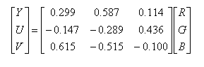
Luminance and chrominance are encoded separately and
transmitted/stored at different bandwidths. In most systems the
chrominance bandwidth is a half (4:2:2 format) or a quarter (4:2:0
format) of the luminance bandwidth. There are several common ways of
transmitting Y, U and V:
- Composite video where Y and the composite sync are combined to
form a 1V peak-to-peak signal. U+V and U-V are used to modulate
orthogonal phases of a color subcarrier (3.58MHz in NTSC broadcasts)
and then mixed with a low-pass-filtered version of Y/sync signal.
- S-Video where Y and the modulated color subcarrier are
transmitted on separate signal/ground pairs. This avoids the low-pass
filtering of Y used in composite video, resulting in a
higher-resolution video image.
- Component video where Y, Cr/Pr, and Cb/Pb are transmitted on
separate signal/ground pairs (Cr and Cb are just scaled versions of U
and V).
Some transmission schemes break a frame into an even field
(containing the even numbered scan lines) and an odd field (containing
the odd numbered scan lines) and then transmit the fields in
alternation. This technique is called interlacing and permits slower
frame rates (and hence lower bandwidths) while still avoiding the
problem of image flicker. When higher bandwidths are available,
non-interlaced transmissions are preferred (often called progressive
scan).
The labkit contains interface chips for encoding (ADV7194) and
decoding (ADV7185) composite and S-Video signals. The decoder chip is
particularly useful if you want to use a video camera signal as part
of your project.
To create a video image for our Pong game, it's helpful to think
of the image as a rectangular array of picture elements or pixels.
There are several common choices for the dimensions (HxV) of the
rectangle:
640x480 (VGA), requires 25MHz (40ns) pixel clock for 60Hz refresh
800x600 (SVGA), requires 40MHz (25ns) pixel clock for 60Hz refresh
1024x768 (XVGA), requires 65MHz (15ns) pixel clock for 60Hz refresh
The computer monitors in the lab support resolutions up to
1280x1024 but the required pixel clock doesn't leave much time for
the game logic to figure out the pixel to display, so let's go with
a 1024x768 display for our game.
Please take a moment to read through the
"VGA Video" hardware tutorial
that's part of the on-line Labkit documentation. You'll see
that the timings for the RGB image information relative to the
horizontal and vertical syncs are somewhat complicated. For example,
the horizontal sync goes active in the interval between the end of one
scan line and the beginning of the next -- the exact timings are
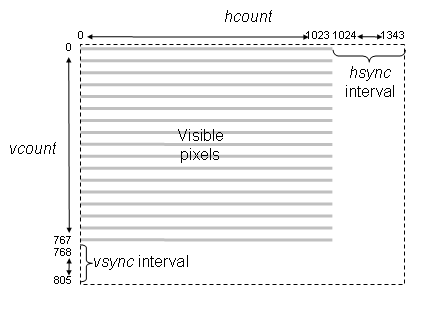
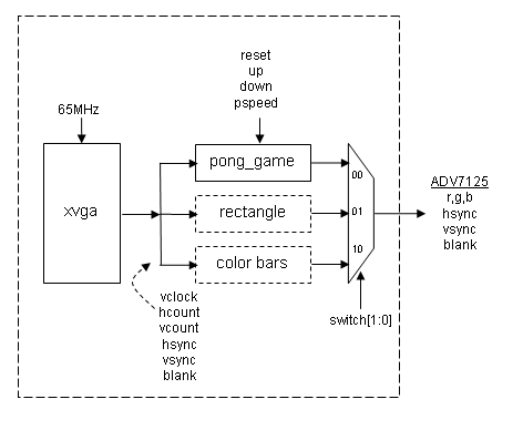
specified by the XVGA specification. Lab3.v includes an xvga
module that generates the necessary signals; it uses two counters:
hcount counts pixels in a horizontal scan line. Values 0
through 1023 are the 1024 displayed pixels, values 1024 through 1343
time the interval between the end of one scan line and the start of
the next. Specific values in this interval are decoded to time the
beginning and end of the active-low horizontal sync signal
(hsync).
vcount counts scan lines in a frame. Values 0 through 767
are the 768 displayed scan lines, values 768 through 805 time interval
between end of one frame and the start of the next. Specific values
in this interval are decoded to time the beginning and end of the
active-low vertical sync signal (vsync).
The xvga module also generates blank, a signal that's
0 when a pixel value will be displayed and 1 when the pixel would be
off the screen (hcount > 1023 or vcount > 767). The inversion
of this signal is required by the AD7125 VGA interface chip
You can use (hcount,vcount) as the (x,y) coordinate of
the pixel to be displayed: (0,0) is the top-left pixel, (1023,0) is
the top-right pixel, (1023,767) is the bottom-right pixel, etc. Given
the coordinates and dimensions of a graphic element, your game logic
can use (hcount,vcount) to determine the contribution
the graphic element makes to the current pixel. If you are storing
the pixels in a memory array (called a frame buffer) then the index of
the current pixel would be
H*vcount + hcount[9:0], where H is the number
of displayed pixels in each scan line.
Images
Generally images are stored in a compressed form to save on space. Two
commonly used formats are PNG (portable network graphics) and JPG (Joint
Photographic Experts Group) formats. PNG is a lossless compression while
JPG is a lossy compression. The human eye, however, generally will not be
able to notice the loss in fidelity with lossy compression. Another format
is BMP, an uncompressed file format. With BMP, the image is stored in a
two dimensional memory (frame buffer) with coordinates ( i,
j) corresponding to the i th column,
j th row pixel in the image. Each pixel can be
represented as single bit (black or white) or up to 24 bits for color. The
image Death Star below is 256 x 240 pixels.
However, frame buffer memory in digital system is generally organized as
a flat one dimensional memory or a linear memory model with an index into a
single contiguous address space. The conversion of the addressing from two
dimensions to linear addressing is straight forward.
For a given pixel of
the image at location ( i, j) of the image, in our Death Star
example, the index in a linear address for that pixel is i + j*256
where 256 is the width of the image.
The video DAC provides for 8 bits RGB for a total of 24 bits.
Using 24 bits is considered to be true color since any color from a
palette of 16 million (2**24) can be displayed. [Note: use "**" for
exponentation and not ^. The symbol ^ is the XOR function in Verilog.]
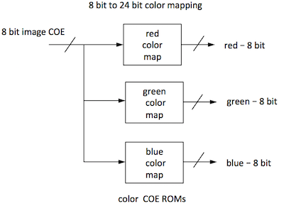
When memory is a constrained and it generally is, a color map is used to reduced
the memory usage yet still display 24 bits of color. This is accomplished by reducing
the palette of 16 million colors available. In our example, using 8 bits for each
pixel we can display 256 different colors. The 8 bit value is then used as an index
to three color maps (for RGB) resulting in the 24 bit value sent to the VGA output. This limits the image
to just 256 colors from a palette of 16 million.
Pong Game
Pong was one of the first mass-produced video games, a hit more
because of its novelty than because of the gaming experience itself.
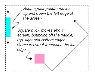
Our version will be a single-player variation where the player is
defending a "goal" by moving a rectangular paddle up and down the left
edge of the screen. The puck (Death Star) moves about the screen with a fixed
velocity, bouncing off the paddle and the implicit walls at the top,
right and bottom edges of the screen. If the puck (Death Star) reaches the left
edge of the screen (i.e., it wasn't stopped by bouncing off the
paddle), the player looses and the game is over:
A 65MHz clock serves as the system clock and times the duration of
a single pixel. The position of moving objects (e.g., the paddle and
puck) are changed once every frame (1/60 second) during the
high-to-low transition of vsync.
To keep the initial implementation easy, let's make the puck a
64-pixel by 64-pixel square and have it move at move diagonally at a
constant velocity. We'll use switch[7:4] to set the puck's
velocity in terms of pixels/frame: 4'b0000 means no motion,
4'b0101 would cause the puck (Death Star) to change both its x and y coordinate
by 5 every frame (the sign of the change for each coordinate would be
determined by which of the 4 possible headings the puck (Death Star) is following
at the moment). When the puck (Death Star) collides with an edge or the paddle,
its heading changes appropriately, e.g., a collision with the bottom
edge changes the sign of the puck's y velocity.
Make the paddle 16 pixels wide and 128 pixels high. It should move
up and down the left edge of the screen at 4 pixels/frame in response
to the user pressing the UP or DOWN buttons on the labkit.
Pressing the ENTER button should reset the game to its initial
state: the paddle centered on the left edge, and the puck (Death Star) somewhere in
the middle of the screen, heading southeast. If the puck (Death Star) reaches the
left edge, the game should stop (it can be restarted by pressing the
ENTER button).
Implementation steps
- Download lab3.v and
labkit.ucf by right clicking on the links
and selecting "Save As", compile it using the Xilinx tools, and then
load it onto the labkit.
[ISE detail: The labkit.ucf file includes constraints for all
of the input and output ports defined in labkit.v. The pong game
will not use all of these signals, in which case the synthesis
engine will optimize the unused signals out of the design. It is
therefore necessary to tell ISE not to generate an error if it
encounters a pin constraint for a (now) unused signal. To do
this, right-click on the "Implement Design" item in the process
pane, and select "Properties...". Check the box to "allow
unmatched LOC constraints".]
Connect the VGA cable from your computer
monitor to the VGA connector on the left-hand side of the labkit's
main board. The VGA cable is the one with blue connector housings
-- the computer is connected to the same monitor with a DVI cable
that has white connector housings. Select the VGA input by pressing
the input select button on the lower right bezel of the monitor
(it's embossed with ---).
Set the labkit's slide switches so that switch[1:0] is 2'b10. You
should see vertical colored bars on the monitor; the color sequence
progresses through the eight possible colors where each of R, G or B
is 8'hFF or 8'h00. If don't see this image, make sure the monitor is
reading from the VGA input, the cable is connected properly and the
download to the FPGA completed successfully.
Now set the slide switches so that switch[1:0] is 2'b01. This
should produce a one-pixel wide white outline around the edge of the
screen. If one or more of the edges isn't visible, the image size and
position can be adjusted using the monitor's controls. Push the
"menu" button and use the "+" and "-" buttons to navigate to the
Position and Size selections. Adjust until all four edges of the
white rectangle are visible.
Finally set the slide switches so that switch[1:0] is 2'b00.
You should see a color checkerboard thats being produced by the
Verilog code inside of pong_game module. This is the code you'll
modify to implement your pong game.
- Modify the pong_game module so that it produces a white
square in the middle of the screen. See the implementation tips below
for some hints about how to do this. The pong_game module has
the following inputs and outputs:
| vclock |
input |
65MHz pixel clock |
| reset |
input |
1 to reset the module to its initial state, hooked to the ENTER pushbutton via a debouncing circuit |
| up |
input |
1 to move paddle up, 0 otherwise. Hooked to the UP pushbutton via a debouncing circuit. |
| down |
input |
1 to move paddle down, 0 otherwise. Hooked to the DOWN pushbutton via a debouncing circuit. |
| pspeed[3:0] |
input |
Puck (Death Star) horizontal & vertical velocity in pixels per frame. Hooked to switch[7:4] |
| hcount[10:0] |
input |
Counts pixels on the current scan line, generated by the xvga module. |
| vcount[9:0] |
input |
Counts scan lines in the current frame, generated by the xvga module. |
| hsync |
input |
Active-low horizontal sync signal generated by the xvga module. |
| vsync |
input |
Active-low vertical sync signal generated by the xvga module. |
| blank |
input |
Active-high blanking signal generated by the xga module. |
| phsync |
output |
Active-low horizontal sync signal generated by your Pong game. Often this is just hsync, perhaps delayed by a vclock if your pixel generating circuitry takes an additional vclock. |
| pvsync |
output |
Active-low horizontal sync signal generated by your Pong game. Often this is just vsync, perhaps delayed by a vclock if your pixel generating circuitry takes an additional vclock. |
| pblank |
output |
Active-high blanking signal generated by your Pong game. Often this is just blank, perhaps delayed by a vclock if your pixel generating circuitry takes an additional vclock. |
| pixel[23:0] |
output |
The {R,G,B} value for the current pixel, eight bits for each color. |
- Now replace the square puck with an image of the Death Star by replacing the blob with
a ROM of the image. To create a ROM, use IP Coregen and follow the instructions
here.
(A ROM in
a FPGA is simply memory initialized with a coefficient (COE) file.)
We took the death star image and extracted
the image and color map files using a MATLAB
script. The image COE file contains 61,442 lines: 256 * 240 = 61440 + 2
lines for the header. The color map files contains 258 lines: 2**8 + 2 lines
for the header. We have already created the COE files for the lab:
[Death Star image COE],
[Death Star color map COE].
(We included instructions for creating your own COE files in the MATLAB script in case you wish
to use your own image.)
The image COE file are the pixels of the image. The color COE files are the
color maps. Create two ROMs using IP Coregen. The image ROM is 61440 x 8. The
color map ROM is 256 x 8. Use the COE files as the initialization file for the ROMs.
For simiplicity, use the same color map COE file all the colors thus
creating a greyscale image. You can experiment and create images of other colors
by varing the ratio of R,G,B.
The generation of the ROMs also results in generated .veo files
in the source folder. The contents of the .veo files list the ports
names of the ROMs.
Here is an example of the contents:
// The following must be inserted into your Verilog file for this
// core to be instantiated. Change the instance name and port connections
// (in parentheses) to your own signal names.

//----------- Begin Cut here for INSTANTIATION Template ---// INST_TAG
image_rom YourInstanceName (
	.clka(clka),
	.addra(addra), // Bus [15 : 0]
	.douta(douta)); // Bus [7 : 0]

// INST_TAG_END ------ End INSTANTIATION Template ---------
Using the ROMs, send the appropropriate pixel based on hcount, vcount.
- Add logic to make the puck (Death Star) move along one of the four possible
diagonal directions, making it "bounce" off the edges of the screen.
The speed of the puck (Death Star) is set by the pspeed input to the pong_game
module.
- Add logic to display a paddle along the left edge of the
screen which moves up and down at 4 pixels/frame in response to the up
and down inputs to the pong_game module.
- Add logic to make the puck (Death Star) bounce off the paddle and
to end the game if the puck (Death Star) reaches the left edge of the screen. The
game should stay halted until the reset input is asserted by pressing
the ENTER button.
- Now create an 128x128 red (color: 24'hFF_00_00) square object (blob) near the center of the screen.
Make the puck (Death Star) appear transparent using alpha bending.
When the puck (Death Star) and object overlap, the resulting rgb value with alpha blending is
[(R,G,B) result] = [(R,G,B) puck ] * α + [(R,G,B) object] * (1- α)
Obviously, α = 0 gives you a completely transparent puck (Death Star),
while α = 1 gives you an opaque puck (Death Star).
Note that each individual color needs
to be multiply by alpha - not the 24 bit value.
R(blended) = R(puck)* α + R(object) * (1- α)
G(blended) = G(puck)* α + G(object) * (1- α)
B(blended) = B(puck)* α + B(object) * (1- α)
Alpha blending is a mathematical operation. Since
Verilog has built in multipers but no dividers (dividers can be
created), we must implement alpha blending by
multiplying and right shifting (dividing by powers of 2).
Express α as m/n where m,n are integers of your choice and n is
a power of 2. (1-α) must be
expressed as a fraction.
- [optional] There are many possible improvements to this
implementation: a two-player version with another paddle along the
right edge of the screen, more interesting puck motion and puck
shapes, sound effects, displaying a score at the top of the screen,
etc. If you have the time and inclination, it can be fun to hack
around a bit!
- [optional - those that want a challenge] Change your
puck drawing logic to draw a circular puck instead of just a
square. Note that the logic needed to compute if
(x-xcenter)*(x-xcenter) + (y-ycenter)*(y-ycenter) is less
than radius*radius probably has a tPD that exceeds one
period of the 65MHz clock. So you'll need to pipeline this
calculation. When you pipeline this calculation other
signals will need to be appropriately delayed.
Implementation Tips
You may find it useful to use the following parameterized module in
your implementation of Pong. Given the pixel coordinate
(hcount,vcount) it returns a non-black pixel if the
coordinate falls with the appropriate rectangular area. The
coordinate of the top-left corner of the rectangle is given by the x
and y inputs; the width and height of the rectangle, as well as its
color, are determined by module's parameters.
//////////////////////////////////////////////////////////////////////
//
// blob: generate rectangle on screen
//
//////////////////////////////////////////////////////////////////////
module blob
   #(parameter WIDTH = 64,            // default width: 64 pixels
               HEIGHT = 64,           // default height: 64 pixels
               COLOR = 24'hFF_FF_FF)  // default color: white
   (input [10:0] x,hcount,
    input [9:0] y,vcount,
    output reg [23:0] pixel);

   always @ * begin
      if ((hcount >= x && hcount < (x+WIDTH)) &&
	 (vcount >= y && vcount < (y+HEIGHT)))
	pixel = COLOR;
      else pixel = 0;
   end
endmodule
You can instantiate several instances of blob to create different
rectangles on the screen, using #(.param(value),...) to specify the instance's
parameters:
reg [9:0]  paddle_y;
wire [23:0] paddle_pixel;
blob #(.WIDTH(16),.HEIGHT(128),.COLOR(24'hFF_FF_00))   // yellow!
     paddle1(.x(11'd0),.y(paddle_y),.hcount(hcount),.vcount(vcount),
             .pixel(paddle_pixel));
[From the "more than you wanted to know" department:] blob
is a very simple example of what game hardware hackers call a
sprite: a piece of hardware that generates a pixel-by-pixel
image of a game object. A sprite pipeline connects the output (pixel
& sync signals) of one sprite to the input of the next. A sprite
passes along the incoming pixel if the object the sprite represents is
transparent at the current coordinate, otherwise it generates the
appropriate pixel of its own. The generated pixel might come from a
small image map and/or depend in some way on the sprite's internal
state. Images produced by sprites later in the pipeline appear in
front of sprites earlier in the pipeline, giving a pseudo 3D look to
the same. This becomes even more realistic if sprites scale the image
they produce so that it gets smaller if the object is supposed to be
further away. The order of the pipeline becomes unimportant if a
"Z" or depth value is passed along the pipeline with each pixel.
The current sprite only replaces the incoming pixel/Z-value if its
Z-value puts it in front of the Z-value for the incoming pixel.
Simple, but sprites produced surprisingly playable games in the era
before the invention of 3D graphic pipelines that can render billions
of shaded triangles per second.]
Here is a modification of the blob module used to display an
image. For simplicity, we use just one color map and displayed
a greyscale image.
////////////////////////////////////////////////////
//
// picture_blob: display a picture
//
//////////////////////////////////////////////////
module picture_blob
   #(parameter WIDTH = 256,     // default picture width
               HEIGHT = 240)    // default picture height
   (input pixel_clk,
    input [10:0] x,hcount,
    input [9:0] y,vcount,
    output reg [23:0] pixel);

   wire [15:0] image_addr;   // num of bits for 256*240 ROM
   wire [7:0] image_bits, red_mapped, green_mapped, blue_mapped;

   // calculate rom address and read the location
   assign image_addr = (hcount-x) + (vcount-y) * WIDTH;
   image_rom  rom1(.clka(pixel_clk), .addra(image_addr), .douta(image_bits));

   // use color map to create 8 bits R, 8 bits G, 8 bits B
   // since the image is greyscale, just replicate the red pixels
   // and not bother with the other two color maps.
   // use color map to create 8bits R, 8bits G, 8 bits B;
   red_coe rcm (.clka(pixel_clk), .addra(image_bits), .douta(red_mapped));
   //green_coe gcm (.clka(pixel_clk), .addra(image_bits), .douta(green_mapped));
   //blue_coe bcm (.clka(pixel_clk), .addra(image_bits), .douta(blue_mapped));

   // note the one clock cycle delay in pixel!
   always @ (posedge pixel_clk) begin
     if ((hcount >= x && hcount < (x+WIDTH)) &&
          (vcount >= y && vcount < (y+HEIGHT)))
        pixel <= {red_mapped, red_mapped, red_mapped}; // greyscale
        //pixel <= {red_mapped, 16h'0}; // only red hues
        else pixel <= 0;
   end
endmodule