Goal: Design a simple circuit to send data from the labkit to a laptop using a serial to USB adapter. (This is useful for transfering images or sound between the labkit and laptop.)
Useful links
Checkoff
Using the labkit, send and display your initials on your laptop with each press of enter. The transmission must be free of errors.
Serial Communications
One of the earliest communications protocol is RS-232 an asynchronous serial protocol commonly referred to as serial. Data is sent over a single wire one bit at a time at a fixed data rate. This form of serial is the same standard used with FTDI chips on Arduino boards or directly to some other microcontrollers over USB. In contrast, SPI and I2C are synchronous protocols which include a clock line. RS232 Data rates can range from 300 bits per second (bps) to megabits/second. (The first modem was 300 bps. When 1200 bps modems came out that was considered high speed - 4 x 300 bps!)
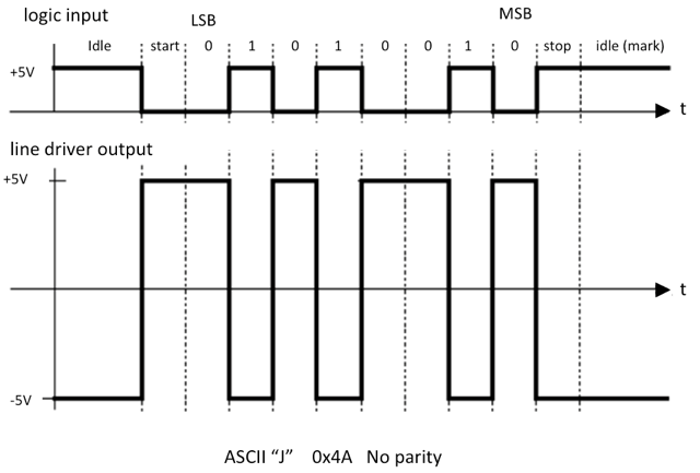
The protocol specifies the number of start bits, data bits (typically 8), parity bit (if any) and stop bit. The start bit indicates the start of the data stream while the stop bit indicates the end. Text is represented as binary data specified in the ASCII (http://www.asciitable.com) table.
The original RS-232 specification has a voltage range of -25V to +25V. The wide voltage range helps with noise immunity. To add to confusion, a logic high (referred to in the spec as "mark") is -25V while a logic low ("space") is +25V. Modern RS-232 serial line drivers such as the one used in the labkit (MAX3222) will (fortunately) accept TTL input voltage levels. There are separate transmit and receive lines allowing for duplex communications. The diagram below show the signal coming out of the labkit for an uppercase J with no parity. Note the inverted logic. The RS232 line driver, MAX3222, handles both the inversion and voltage level conversion.
Straight Through Cable or Cross Over-Null Modem Cable?
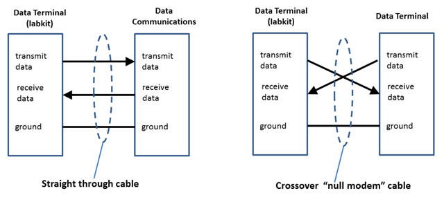
In RS-232, a terminal (the labkit, a DTE data terminal equipment) will send data out over the transmit line to a host or modem (DCE data communications equipment). For DTE, the transmit signal is an output while for DCE, transmit is an input. Similarly for a terminal (DTE) receive is an input while for DCE, receive is an output. When a terminal is attached to a modem, a straight through cable is used.
When a terminal is attached to another terminal (i.e. Arduino to Arduino) a cross over (aka null modem) cable is used to connect the transmit line of one device to the receive line of the other device.
In ancient times (pre-1995), data rates were faster than what systems could handle. One solution is hardware flow control signals such as Data Terminal Ready (DTR), Data Set Ready (DSR), Request to Send (RTS) and Clear To Send (CTS). Flow control can also be implemented with special characters (XON - CTRL S and XOFF - CTRL C). Today's systems can easily handle most serial data rates so flow control is generally not necessary.
In this lab, you will create Verilog to send ASCII data from the labkit (a DTE device) to a USB adapter and display the character on your laptop. A few lines of python will be required to setup the serial port and read the data at the computer end.
Serial Transmitter - "Serializer"
The goal of this lab is to implement a serializer that takes a byte of data from the labkit and sends it out a bit at time with a clock to a laptop. The data is set by eight switches and transmitted when the enter button is pressed.
Step 0: Getting started with the serial lab
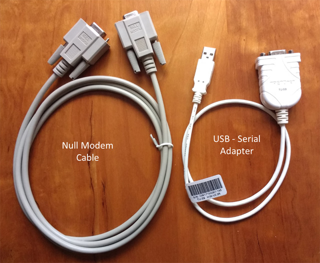
Null Model Cable & USB-Serial Adapter
The USB adapter uses the Prolific pl2303 chipset for the serial to USB
conversion. No drivers are required for Ubuntu. Drivers are available for
macOS (10.9-10.12) and for
Windows 7-10.
http://web.mit.edu/6.111/www/f2017/drivers/MAC/MacOSX_1.6.1_20160309.pkg
http://web.mit.edu/6.111/www/f2017/drivers/Windows/PL2303%20Windowsv1.12.0.pdf
Depending on the operating system, serial port will show as:
macOS: 10.9 Maverick, 10.10 Yosemite, 10.11 El Capitan, 10.12 Sierra
serial port: /dev/tty.usbserial
In a terminal window, use ls /dev/tty.*
Windows: Windows 7 and higher
device name: Prolifc USB-to-Serial Comm Port
serial port: COM3 or higher
See com ports under "Device Manager"
Ubuntu: 14.04
device name: Prolific Technology, Inc. PL2303 Serial Port
serial port: /dev/ttyUSB0 or higher
In a terminal window use dmesg | grep tty
Step 1: Hooking up the hardware
Attached the null modem cable to the labkit and USB adapter.
Install Python 3.x followed by pyserial (or your favorite serial program) on your laptop.
Step 2: Program the labkit
A compiled Verilog bitfile has been set up for 115 Kbps with one start bit, 8 bit data, no parity and one stop bit to test your setup: rs232.bit. Download the file to an appropriate folder.
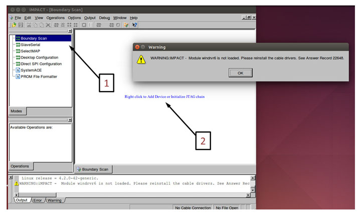
Load the bitfile to the labkit by running IMPACT in a terminal window. Select Boundary Scan [1] and right click [2] to initialize the JTAG programming. To program the FPGA, bypass "xccae" and "xcf32p" and right click on xc2v6000 and program. Ignore the warnings "Module windrv6 not loaded".
If correcty programmed, the eightswitches will control the leds and displays the character on the 16 alphanumeric display.
Step 3: Checkout the hardware
It would be frustrating to have correct Verilog only to discover a hardware or cable problem. This simple check avoids that situation. Attached the USB adapter to your laptop. If everything is setup correctly, you should be able to send ASCII text from the labkit to your laptop. Each press of the enter button will send data set by SWITCH[7:0] to the serial port. Here is a basic python script python script on a MAC to read data from the labkit:
import serial
import time
from time import sleep

# configure the serial connections
ser = serial.Serial(
    port='/dev/tty.usbserial',
    baudrate=115200,
    parity=serial.PARITY_NONE,
    stopbits=serial.STOPBITS_ONE,
    bytesize=serial.EIGHTBITS,
    timeout=0)

# open the serial port
if ser.isOpen():
     print(ser.name + ' is open...')

while True:
    data = ser.read(99)
    if len(data) > 0:
        print(data)

    sleep(5.0)
    print ('checking')

ser.close()
For other operating system, replace /dev/tty.usbserial with the approporate port name. Alternatively, we have a
more fancy program that auto-detects the ports. Try it and let the staff know if you have problems.
'''Automatically find USB Serial Port
jodalyst 9/2017
'''

import serial.tools.list_ports
import sys
import time
from time import sleep
#Version 2.7 or Above?
if sys.version_info[0] >2:
    version3 = True
    kwargs = {'newline':''}
else:
    version3 = False
    kwargs = {}

def get_usb_port():
    usb_port = list(serial.tools.list_ports.grep("USB-Serial Controller"))
    if len(usb_port) == 1:
        print("Automatically found USB-Serial Controller: {}".format(usb_port[0].description))
        return usb_port[0].device
    else:
        ports = list(serial.tools.list_ports.comports())
        port_dict = {i:[ports[i],ports[i].vid] for i in range(len(ports))}
        usb_id=None
        for p in port_dict:
            print("{}:   {} (Vendor ID: {})".format(p,port_dict[p][0],port_dict[p][1]))
            if port_dict[p][1]==1659:
                usb_id = p
        if usb_id== None:
            return False
        else:
            print("USB-Serial Controller: Device {}".format(p))
            return port_dict[usb_id][0].device

s = get_usb_port()
if s:
    ser = serial.Serial(port = s,
        baudrate=115200,
        parity=serial.PARITY_NONE,
        stopbits=serial.STOPBITS_ONE,
        bytesize=serial.EIGHTBITS,
        timeout=0) #auto-connects already I guess?
    print(ser)
    print("Serial Connected!")

    if ser.isOpen():
         print(ser.name + ' is open...')

    while True:
        data = ser.read(99)
        if len(data) > 0:
            if version3:
                print(data.decode('ascii'))
            else:
                print(data)

        sleep(3.0)

    ser.close()
else:
    print("USB-Serial Controller Not Found")
Step 4: Implementation
Now the slide switches set the ASCII code and is displayed in binary on the leds. The character is also displayed on the 16 alphanumeric display. rs232send module at this point does nothing. No characters are sent.
| clk | input | system 27mhz clock |
| data | input | 8 bits ASCII encoded data (non-inverted) |
| xmit_data | output | 1 bit output sent to line driver ( non-inverted) |
| start_send | input | enter button pressed - one clock pulse width, synchronized |
| xmit_clk | output | clock used to shift out data - one clock pulse width |
| DIVISOR | parameter | divisor needed to create xmit_clk from 27mhz (see Verilog) |
Design alternatives: If you view the problem from a digital hardware approach, create a shift register and send the data out with each clock pulse. Looking at it from a software approach, create an array where each element is a bit, send out each element then increment the index and repeat.
Here's one digital hardware approach. When start_send is asserted, data is available to be transmitted. The easiest approach is to use a 10 bit shift register. With start_send, load the data along with the start and stop bits into the shift register. With each xmit_clk shift the data out with the high order stop bit shifted in.
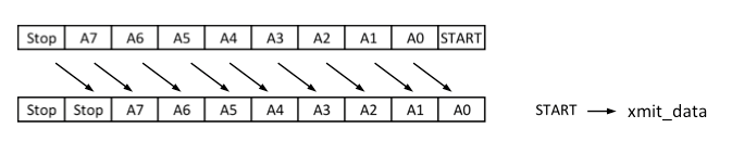
When all the bits are shift out, the output is held in idle by continually sending out stop bits. When your circuit is working, ask a staff member to check you off. (1 point) For checkoff be prepared to show your circuit in operation displaying your initials on the laptop.
After checkoff, please upload your Verilog file using the "Submit Verilog" page on the course website. We'll review your code and post some comments to help you improve your Verilog style.
Please return the cable and USB adapter to the TA station.
Receiving data is slightly more complicated. Avoid the temptation to use an edge as an input. Using an input edge as a signal is poor design since any noise will initiate the process. A better approach is to oversample, e.g., at 16x baud rate. Look for 1->0 transition at beginning of start bit. Count to 8 to sample start bit, then repeatedly count to 16 to sample other bits. Check format (start, data, parity, stop bits) before accepting data.