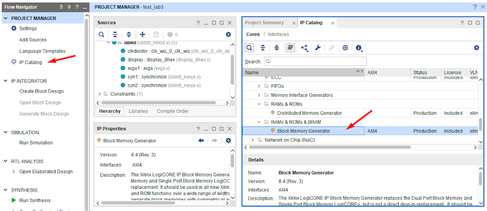
Under your project add a new source using IP Catalog and select "Block Memory Generator" [Click]. Block memory is
silicon in the FPGA dedicated and optimized for creating memory. Distribured memory creates memory by using
flip flops when performance is needed but consumes significant resources and area on the chip.
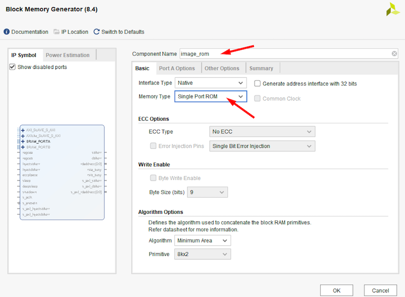
Create a single port ROM and and give it a filename [image_rom in this example] in your
project folder.
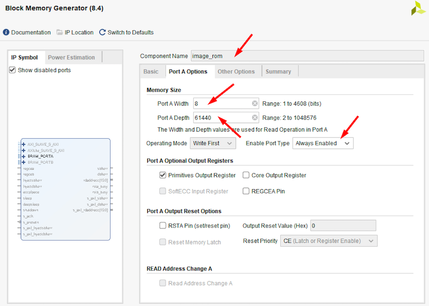
Under Port A Options, create the 8 bit wide ROM for a 256x240 image (= 61440 depth).
Select "Always Enabled". Otherwise
an enable port must be created. If not, a black screen will result.
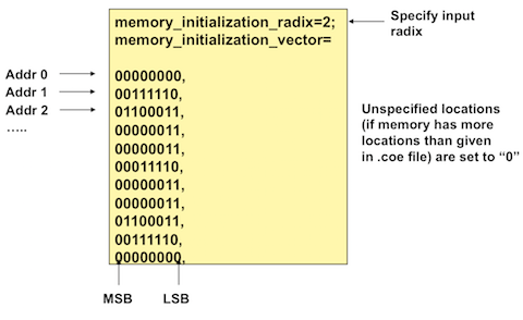
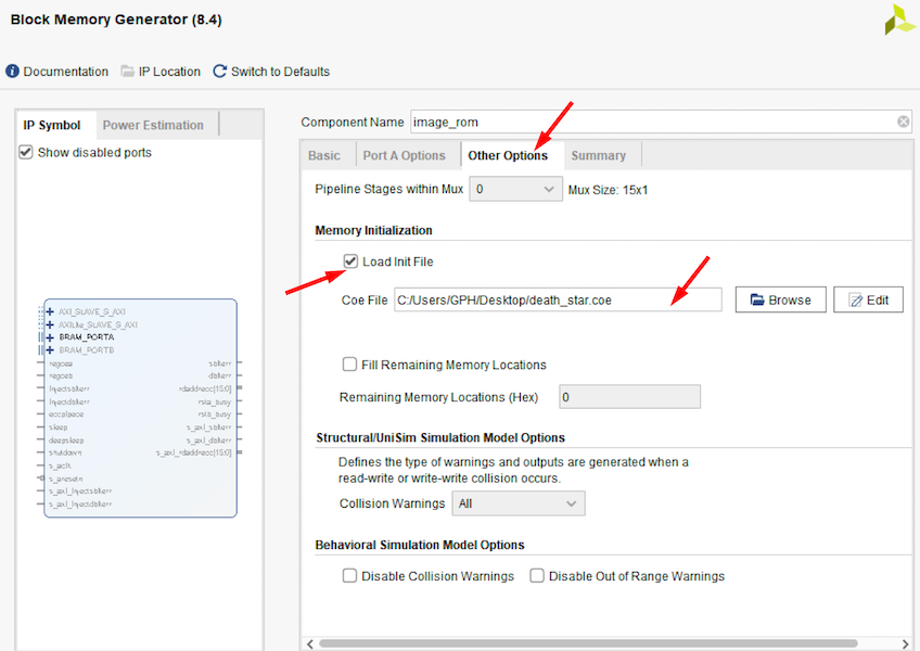
For ROMs, the memory is initialized with COE files. Under Other Options, provide a memory initization
(COE) file and check "Load Init File".
The generation of the ROMs creates .veo files
in the project folder. The contents of the .veo files list the ports
names needed to instantiate the ROM memory.
Here is an example of the port names for our image rom:
