 Notta has noticed the following C code fragment appears frequently in the benchmarks:
   int *p;     /* Pointer to integer array */
   int i,j;    /* integer variables */
   ...
   j = p[i];   /* access ith element of array */
The pointer variable p contains the address of a dynamically
allocated array of integers. The value of p[i] is stored at the
address Mem[p]+4*Mem[i] where p and i are locations containing the values of
the corresponding C variables. On a conventional Beta this code
fragment is translated to the following instruction sequence:
   LD(...,R1)     /* R1 contains p, the array base address */
   LD(...,R2)     /* R2 contains I, the array index */
   ...
   SHLC(R2,2,R0)  /* compute byte-addressed offset = 4*i */
   ADD(R1,R0,R0)  /* address of indexed element */
   LD(R0,0,R3)    /* fetch p[i] into R3 */
Notta proposes the addition of an LDX instruction that shortens the
last three instructions to
   SHLC(R2,2,R0)  /* compute byte-addressed offset = 4*i */
   LDX(R0,R1,R3)  /* fetch p[i] into R3 */
Give a register-transfer language description for the LDX
instruction. Examples of register-transfer language descriptions can
be for other Beta instructions in the Beta Documentation handed out in
lecture.
LDX( Ra, Rb, Rc )
    EA <- Reg[Ra] + Reg[Rb]
    Reg[Rc] <- Mem[EA]
    PC <- PC + 4
It occurs to Notta that adding an STX instruction would probably be
useful too. Using this new instruction, p[i] = j might compile into
the following instruction sequence:
   SHLC(R2,2,R0)  /* compute byte-addressed offset = 4*i */
   STX(R3,R0,R1)  /* R3 contains j, R1 contains p */
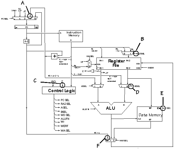
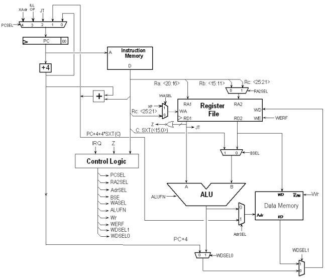
Briefly describe what modifications to the Beta datapath would be
necessary to be able to execute STX in a single cycle.
The register transfer language description of STX would be:
STX(Rc, Rb, Ra)
    EA <- Reg[Ra] + Reg[Rb]
    Mem[EA] <- Reg[Rc]
    PC <- PC + 4
It's evident that we need to perform 3 register reads, but the Beta's
register file has only 2 read ports. Thus we need to add a third read
port to the register file.
Incidentally, adding a third read port would eliminate the
need for the RA2SEL mux because we no longer need to choose between Rb
and Rc, since each register field has its own read port.
 In an unpipelined Beta implementation, when is the signal
RA2SEL set to "1"?
 In an unpipelined Beta implementation, when executing a
BR(foo,LP) instruction to call procedure foo, what should WDSEL should
be set to?
 The minimum clock period of the unpipelined Beta implementation
is determined by the propagation delays of the data path elements and
the amount of time it takes for the control signals to become valid.
Which of the following select signals should become valid first in
order to ensure the smallest possible clock period: PCSEL, RA2SEL,
ASEL, BSEL, WDSEL, WASEL?


