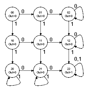
Problem 1. (Katz, problem 8.13) A finite state machine has one input and one output. The output becomes 1 and remains 1 thereafter when at least two 0's and two 1's have occurred as inputs, regardless of the order of appearance.
-
Assuming this is to be implemented as a Moore machine, draw a
state transition diagram for the machine. Hint: You can do this
in nine states.
-
Write a Verilog module that implements the machine. Your module
should have the following inputs/outputs.
-
CLK
- used to clock the FSM
- asserted high to reset the FSM to its initial state
- asserted high to input a "1". Note that this signal
may stay high for many cycles (eg, it's generated by a button press)
before returning low. Each high period should count as a single
"1" input, ie, to inputs two "1"s in series, the signal must return
low inbetween the first and second "1".
- asserted high to input a "0". This signal has the
same timing protcol as ONE above.
- asserted high when at least two "0"s and two "1"s
have occurred as inputs.
module fsm01(clk,reset,one,zero,out);
  // state assignments
  parameter STATE_0_0 = 0;     // 0 zeroes, 0 ones
  parameter STATE_0_1 = 1;     // 1 zero, 0 ones
  parameter STATE_0_2 = 2;     // 2 zeroes, 0 ones
  parameter STATE_1_0 = 3;     // 0 zeroes, 1 one
  parameter STATE_1_1 = 4;     // 1 zero, 1 one
  parameter STATE_1_2 = 5;     // 2 zeroes, 1 one
  parameter STATE_2_0 = 6;     // 0 zeroes, 2 ones
  parameter STATE_2_1 = 7;     // 1 zero, 2 ones
  parameter STATE_2_2 = 8;     // 2 zeroes, 2 ones

  input clk,reset,one,zero;
  output out;

  // level-to-pulse converters for ZERO and ONE inputs
  reg last_one,last_zero;
  wire input_one,input_zero;
  always @ (posedge clk)
  begin
    last_one <= reset ? 0 : one;
    last_zero <= reset ? 0 : zero;
  end
  assign input_one = ~last_one & one;
  assign input_zero = ~last_zero & zero;

  // fsm
  reg [3:0] state;
  always @ (posedge clk)
  begin
    if (reset) state <= STATE_0_0;
    else case (state)
     STATE_0_0: state <= input_one ? STATE_1_0 : input_zero ? STATE_0_1 : state;
     STATE_0_1: state <= input_one ? STATE_1_1 : input_zero ? STATE_0_2 : state;
     STATE_0_2: state <= input_one ? STATE_1_2 : state;
     STATE_1_0: state <= input_one ? STATE_2_0 : input_zero ? STATE_1_1 : state;
     STATE_1_1: state <= input_one ? STATE_2_1 : input_zero ? STATE_1_2 : state;
     STATE_1_2: state <= input_one ? STATE_2_2 : state;
     STATE_2_0: state <= input_zero ? STATE_2_1 : state;
     STATE_2_1: state <= input_zero ? STATE_2_2 : state;
     STATE_2_2: state <= state;
     default: state <= STATE_0_0;    // transition out of unused states
    endcase
  end

  // it's a Moore machine so output only depends on current state.
  // Note: OUT might glitch as the logic decodes the current state.
  assign out = (state == STATE_2_2);

endmodule
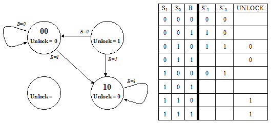
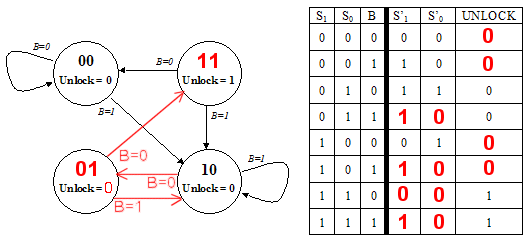
Problem 2. The ACME Company has recently received an order from a Mr. Wiley E. Coyote for their all-digital Perfectly Perplexing Padlock. The P3 has two buttons ("0" and "1") that when pressed cause the FSM controlling the lock to advance to a new state. In addition to advancing the FSM, each button press is encoded on the B signal (B=0 for button "0", B=1 for button "1"). The padlock unlocks when the FSM sets the UNLOCK output signal to 1, which it does whenever the last N button presses correspond to the N-digit combination.-
Unfortunately the design notes for the P3 are incomplete. Using the
specification above and clues gleaned from the partially completed
diagrams below fill in the information that is missing from the state
transition diagram with its accompanying truth table. When done
- each state in the transition diagram should be assigned a 2-bit state name S1S0 (note that in this design the state name is not derived from the combination that opens the lock),
- the arcs leaving each state should be mutually exclusive and collectively exhaustive,
- the value for UNLOCK should be specified for each state, and
- the truth table should be completed.
-
What is the combination for the lock?
100
Problem 3. Construct a "divisible-by-3" FSM that accepts a binary number entered one bit at a time, most significant bit first, and indicates with a light if the number entered so far is divisible by 3.-
Draw a state transition diagram for your FSM indicating the
initial state and for which states the light should be turned on.
Hint: the FSM has 3 states.
If the value of the number entered so far is N, then after the digit b is entered, the value of the new number N' is 2N + b. Using this fact:
-
if N is 0 mod 3 then for some p, N = 3p + 0. After
the digit b is entered, N' = 6p + b. So N' is b mod 3.
if N is 1 mod 3 then for some p, N = 3p + 1. After
the digit b is entered, N' = 6p + 2 + b. So N' is b+2 mod 3.
if N is 2 mod 3 then for some p, N = 3p + 2. After
the digit b is entered, N' = 6p + 4 + b. So N' is b+1 mod 3.

-
Construct a truth table for the FSM logic. Inputs include
the state bits and the next bit of the number; outputs include
the next state bits and the control for the light.
S1 S0  b | S1' S0' light
=========|==============
 0  0  0 |  0   0    1
 0  0  1 |  0   1    1
 0  1  0 |  1   0    0
 0  1  1 |  0   0    0
 1  0  0 |  0   1    0
 1  0  1 |  1   0    0
-
Draw a logic schematic for the FSM.
        __ __
light = S1*S0
      __    _      __
S1' = S1*S0*b + S1*S0*b
      __ __        __ _
S0' = S1*S0*b + S1*S0*b
Problem 4.-
An FSM, M, is constructed by connecting the output of a 3-state
FSM to the inputs of an 9-state FSM. M is then reimplemented using
a state register with the minimum number of bits. What is the
maximum number of bits that may be needed to reimplement M?
M has 27 states which require a total of 5 bits in the state register (not 2 + 4 bits!).
-
You connect M N-state FSMs, each have 1 input and 1 output, in
series. What's an upper bound on the number of states in the
resulting FSM?
Each FSM can in theory be in one of its N states, so an upper bound on the number of states in the combined machine is NM.
Problem 5. Ben Bitdiddle has designed an electronic lock with three buttons: "reset", "0" and "1". He has provided the following state transition diagram showing how the lock responds to a sequence of inputs.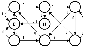
-
After pressing the "reset" button what is the length of the
shortest sequence of button presses that will open the lock?
3 button presses will open the lock: 0, 0, 1.
-
After pressing the "reset" button what is the length of the
longest sequence of button presses that will cause the lock to open
after the last button in the sequence is pressed but not open any
earlier in the sequence?
The longest such sequence is unbounded: any number of 0's followed by 111 or 1111 will cause the lock to open for the first time.
-
After much use, the "reset" button breaks. Is it still
possible to open the lock using only the "0" and "1" buttons assuming
you know nothing about the lock's state (except that its locked!) when
you start?
Yes. A sequence of 1's will open the lock. You have to try the lock after each press of "1" since a different number of 1's is required depending on the starting state.
-
Suppose Ben wanted to design a lock that required exactly 10
button presses to open after pressing "reset". Not counting the
"reset" and "unlock" states, what is the minimum number of state
his FSM would need need?
His FSM would need 9 states in addition to "reset" and "unlock".
Problem 6. Stimulated by the idea of FSMs, you have decided to cover MIT's steep tuition costs by selling simple digital locks based on the following six-state FSM: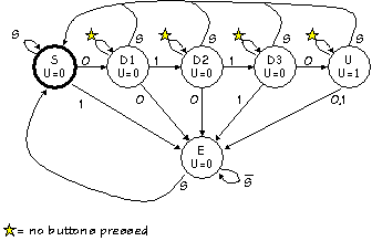 Recall that this design has three buttons labeled "0", "1", and
"Start", and generates an unlock signal U=1 when the user presses
Start followed by the sequence 0,1,1,0.
Unfortunately your partner, Mark Ting, insists that the
design is way too complex for normal users to understand. After asking
you to help figure out how to make his watch stop beeping ("I never
could figure out how to operate this damned thing"), Mark questions
the need for a Start button. If 0110 is the combination, he argues,
why can't I just walk up and enter 0,1,1,0 and have the lock open?
After some reflection, you conclude that he may have a point.
-
Design a FSM whose inputs are simply "0" and "1" buttons, whose output
is the U (unlock) signal, and which has the property that U=1 if and
only if the last four button presses correspond to the sequence
0,1,1,0. Show the state transition diagram corresponding to your
design. [HINT: 5 states are sufficient].
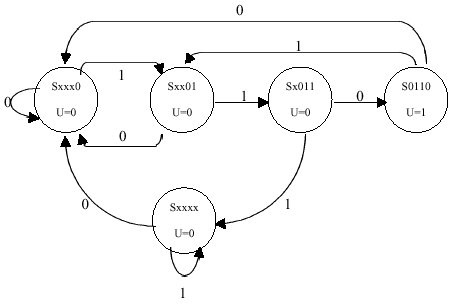 The name of each state represents how many digits in the sequence
have been input. State Sxxxx indicates that the sequences has not begun,
Sxxx0 indicates that the first 0 has been input, etc.
-
Is it possible that an equivalent FSM might be implemented in fewer
than 5 states? Explain.
Since 4 transitions are required for 4 button pushes, at least 5 states are needed to implement the FSM. Having only 4 states would make 3 the mininum number of transitions to the unlock state.
-
The flip flops used to hold your FSM state contain random values when
power is first applied to your lock. Does this constrain your
handling of unused states? Explain.
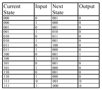
Since we have 5 states, 3 bits are required to encode the states, resulting in 3 unused states. If during power up it is possible to being in an unknown state, our FSM must include transitions from unknown states to known states. If the machine beings in an unknown state and a 0 in input, we should transition to state Sxxx0; if a 1 is input, we should transition to Sxxxx.
-
In a table give the contents of a
ROM that might be used in an implementation of your design. Completely
specify the ROM contents, including those corresponding to unused
states.
Problem 7. A possible implementation of a finite state machine with one input and one output is shown below.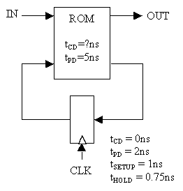
-
If the register is N bits wide, what is the appropriate size of the ROM?
Give the number of locations and the number of bits in each location.
2N+1 locations of N+1 bits.
-
If the register is N bits wide, what is the least upper bound on the
number of states in a FSM implemented using this circuit?
2N
Problem 8. Ben Bitdiddle has designed an electronic lock with three buttons: "Breset", "B0" and "B1". He has provided the following circuit diagram showing how the lock is implemented from a ROM and 3 flip-flops.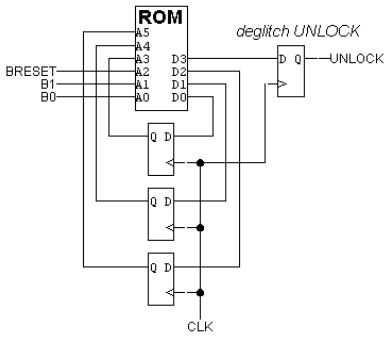 The button circuitry converts each button press into a single pulse
guaranteed to be stable the required amount of time before and after
the rising edge of the clock. For example, pressing "B0" once
produces the following waveform:
 In answering the questions below, assume that the value of the
UNLOCK output is only a function of the current state.
-
What is the total number of bits in the ROM?
256 bits total: 26 locations, 4 bits wide.
-
The timing specifications for components are:
-
ROM: tCD=3ns, tPD=11ns
D flip-flop: tCD=2ns, tPD=4ns, tS=3ns, tH=3ns
tPD,ROM + tS = 14ns.-
Assume that all combinations start with pressing the "Breset"
button. Ben wants to program the lock with the longest possible
combination. Not counting the "Breset" button press, what is the
longest combination Ben can achieve?
7 assuming no looping combinations.
-
If the lock is programmed not to change state if no buttons are
pressed, what is the next state field of ROM location 48 (i.e., the
location corresponding to A5,A4,A3,A2,A1,A0 = 110000)?
The current state appears on A5,A4,A3 = 110. So we want the next state field of the ROM (D2,D1,D0) to specify the same state = 110.
-
The following table shows one possible contents of the first 32
locations of the ROM; assume that all other locations have the value
"0010". The location is listed as A5,A4,A3,A2,A1,A0, the data is listed as
D3,D2,D1,D0.
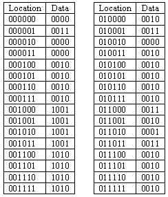 If the lock is programmed with this ROM data, what happens when
"B0" and "B1" are pressed at the same time? Assume that "Breset" is
not pressed.
State stays the same since all addresses of the form XXX011 transition to state XXX.
If the lock is programmed with this ROM data, what happens when
"B0" and "B1" are pressed at the same time? Assume that "Breset" is
not pressed.
State stays the same since all addresses of the form XXX011 transition to state XXX.-
If the lock is programmed with this ROM data, what is the
shortest combination that opens the lock after "Breset" has been
pressed?
press B0, then B1.
-
Suppose that the "Breset" button breaks while the lock is
locked. Is it still possible to open the lock using a predetermined
sequence of presses of the "B0" and "B1" buttons? Assume you know
nothing about the lock's state (except that it's locked!) when you
start.
Yes, you can open the lock. Noting that the UNLOCK state loops to iteself, B1-B0-B1 is one of many sequences that takes us from any state to UNLOCK.
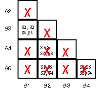
Problem 9. Consider the following FSM state transition diagram: Let's see if there is an equivalent state machine with fewer states
by checking to see if any states in the diagram above are equivalent.
Two states are equivalent if (1) they have identical outputs and (2)
for each possible combination of inputs they transition to equivalent
states.
-
Start by filling in a "compatibility table" like the one shown below.
Place an "X" in square (SI,SJ) if SI produces a different output from
SJ.
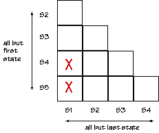
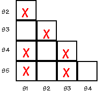
-
For each non-X square (SI,SJ) write in pairs of states that have to be
equivalent in order for SI and SJ to be equivalent. For example, for
S2 to be equivalent to S5, then S1 (where S2 goes with a "0" input)
has to be equivalent to S5 (where S5 goes with a "0" input).
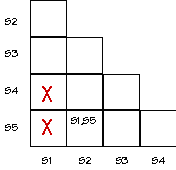
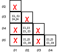
- Finally, look at an entry (SI,SJ). If entry is "SM,SN" and if (SM,SN) has an "X", put an "X" in square (SI,SJ). Repeat until no more squares can be X'ed out. The remaining squares indicate equivalent states. Show the final state (no pun intended) of your compatibility table.
-
For each non-X square (SI,SJ) write in pairs of states that have to be
equivalent in order for SI and SJ to be equivalent. For example, for
S2 to be equivalent to S5, then S1 (where S2 goes with a "0" input)
has to be equivalent to S5 (where S5 goes with a "0" input).
-
Start by filling in a "compatibility table" like the one shown below.
Place an "X" in square (SI,SJ) if SI produces a different output from
SJ.
-
Suppose that the "Breset" button breaks while the lock is
locked. Is it still possible to open the lock using a predetermined
sequence of presses of the "B0" and "B1" buttons? Assume you know
nothing about the lock's state (except that it's locked!) when you
start.
-
If the lock is programmed with this ROM data, what is the
shortest combination that opens the lock after "Breset" has been
pressed?
-
The following table shows one possible contents of the first 32
locations of the ROM; assume that all other locations have the value
"0010". The location is listed as A5,A4,A3,A2,A1,A0, the data is listed as
D3,D2,D1,D0.
-
If the lock is programmed not to change state if no buttons are
pressed, what is the next state field of ROM location 48 (i.e., the
location corresponding to A5,A4,A3,A2,A1,A0 = 110000)?
-
Assume that all combinations start with pressing the "Breset"
button. Ben wants to program the lock with the longest possible
combination. Not counting the "Breset" button press, what is the
longest combination Ben can achieve?
-
The timing specifications for components are:
-
What is the total number of bits in the ROM?
-
If the register is N bits wide, what is the least upper bound on the
number of states in a FSM implemented using this circuit?
-
If the register is N bits wide, what is the appropriate size of the ROM?
Give the number of locations and the number of bits in each location.
-
In a table give the contents of a
ROM that might be used in an implementation of your design. Completely
specify the ROM contents, including those corresponding to unused
states.
-
The flip flops used to hold your FSM state contain random values when
power is first applied to your lock. Does this constrain your
handling of unused states? Explain.
-
Is it possible that an equivalent FSM might be implemented in fewer
than 5 states? Explain.
-
Design a FSM whose inputs are simply "0" and "1" buttons, whose output
is the U (unlock) signal, and which has the property that U=1 if and
only if the last four button presses correspond to the sequence
0,1,1,0. Show the state transition diagram corresponding to your
design. [HINT: 5 states are sufficient].
-
Suppose Ben wanted to design a lock that required exactly 10
button presses to open after pressing "reset". Not counting the
"reset" and "unlock" states, what is the minimum number of state
his FSM would need need?
-
After much use, the "reset" button breaks. Is it still
possible to open the lock using only the "0" and "1" buttons assuming
you know nothing about the lock's state (except that its locked!) when
you start?
-
After pressing the "reset" button what is the length of the
longest sequence of button presses that will cause the lock to open
after the last button in the sequence is pressed but not open any
earlier in the sequence?
-
After pressing the "reset" button what is the length of the
shortest sequence of button presses that will open the lock?
-
You connect M N-state FSMs, each have 1 input and 1 output, in
series. What's an upper bound on the number of states in the
resulting FSM?
-
An FSM, M, is constructed by connecting the output of a 3-state
FSM to the inputs of an 9-state FSM. M is then reimplemented using
a state register with the minimum number of bits. What is the
maximum number of bits that may be needed to reimplement M?
-
Draw a logic schematic for the FSM.
-
Construct a truth table for the FSM logic. Inputs include
the state bits and the next bit of the number; outputs include
the next state bits and the control for the light.
-
Draw a state transition diagram for your FSM indicating the
initial state and for which states the light should be turned on.
Hint: the FSM has 3 states.
-
Unfortunately the design notes for the P3 are incomplete. Using the
specification above and clues gleaned from the partially completed
diagrams below fill in the information that is missing from the state
transition diagram with its accompanying truth table. When done
-
Write a Verilog module that implements the machine. Your module
should have the following inputs/outputs.


