Goal: In this lab, you will design finite state machine(s) to learn four Sony Infrared Command (SIRC) and use it to control a Sony television. (10/2016)
Useful links
Checkoff List
Show to TA at beginning of checkoff:
Be able to demonstrate your working lab:
Be able to respond to any of the following questions and possibly others:
[Checkoff: 4 points, 5 points preprogrammed controls -- see the end]
When you're done remember to upload your Verilog files to the course website so that they can be reviewed.
Infrared Remote Control
Serial communications, where data is transmitted over a single channel one bit at a time, is used every where. Examples are PS/2 mouse and keyboard, USB port and PCI-Express in newer PCs. Another example is the wireless infrared remote control used for TVs and stereo. Serial communications is in contrast to sending many bits in parallel, for example the parallel port on older PCs. Serial communications saves on cable pins, wires and cost. However, to implement serial communications, you need a serializer at the transmitter end and a deserializer at the receiver. (See 6.111 Fall 2008 Lecture 14 [PDF] for more details.
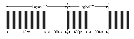
For the wireless remote, the communications channel/medium is infrared light at 950 nm wavelength. Sony uses a 12 bit, 15 bit and 20 bit protocol. We will be using the 12 bit pulse-width modulated serial protocol. With this protocol, a data 1 is 1200 us and a data 0 is 600 us. Bits are separated by 600us. (Picture from www.sbprojects.com/ir/sirc.htm) Commands are sent every 45 milliseconds.
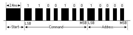
During the on time, the signal is a 40 kHz square wave. For simplicity, we will not show the 40 kHz carrier in future timing waveforms. The format of the data stream is shown below. In this example a command 19 (volume lower) is issued for the TV (from www.sbprojects.com/ir/sirc.htm). A partial listing of the commands is attached at the end.
With this protocol, the length (duration) of each command is a function of the data.
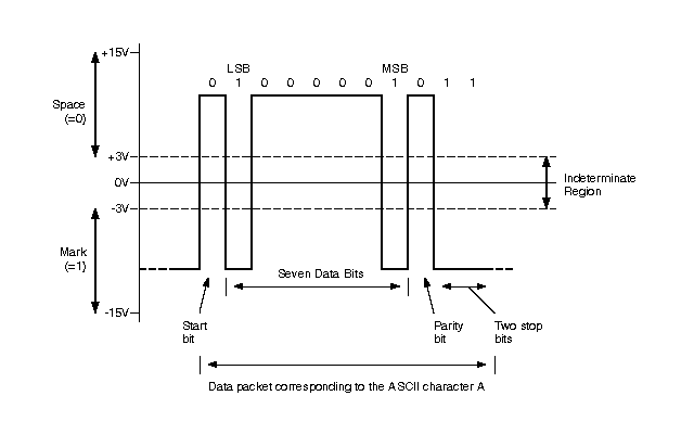
RS-232 and the PS/2 serial protocol use a fixed data time for each bit. The data rate is independent of the data and is purely a function of the bit (baud) rate. See figure below (from http://www.arcelect.com/rs232.htm)
Procedure
The Lab exercise consists of two parts. You will wire up a simple circuit with an infrared LED transmitter, compile a Verilog source file that we provide and verify that the circuit controls the TV. The source file contains the FSM that creates the 40 kHz carrier and serializes the data stream to the infrared LED. In the second part you will wire an infrared receiver and design a FSM that learns new Sony commands and stores the command for use. While the data rate for IR controls is such that a FGPA is not really needed and can be implemented with software, the design principles are applicable at much higher data when hardware must be used.
The following diagram illustrates a possible organization of your design. This diagram is a high level view and does not show every necessary signal.
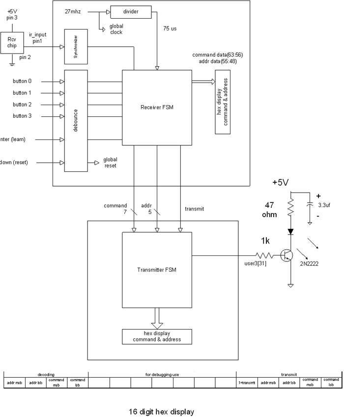
Step 1:
Wire up the infrared led transmitter (Vishay TSKS5400S Infrared Emitting Diode, 950 nm, GaAs) on your protoboard. The led is the blue component.
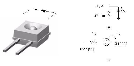
The pin out for the 2N2222 BJT is shown below. Note that the collector (pin 3) is connected electrically to the case!
Compile and load the bit file. Verify that this changes the channel on the TV using the up button. The command and the address are displayed on the led display. Observe the signal from the user output on an oscilloscope.
Step 2:
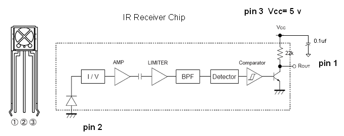
Wire up the infrared receiver (RPM7140-R) on your protoboard. The receiver is an integrated infrared digital chip that demodulates the 40 kHz signal and provides an inverted output signal to the labkit. The output of the receiver (pin 1) is the input signal to the labkit. All that is required is to supply Vcc = 5V and ground. (You may keep the components in this lab for your personal use.)
Your task is to design and implement a digital system that will read the data from the remote control unit, learn the command and then transmit the commands using button 0, 1, 2 and 3 with your transmitter.
IR Receiver FSM Design Requirements
With serial communications, incoming data may be glitchy. For that reason, it is not good design practice to use an edge as a trigger [example: "always @ (posedge data)" ]. For this lab, your receiver FSM must be implemented by oversampling the incoming data at 75 us (600us/8). With sampling, the probability of an error is greatly reduced since the glitch must coincide with the sampling. Be sure to synchronize your IR input!
Design and implementation suggestions:
Sony Commnands (Partial Listing)
Preprogrammed Controls
For full credit add one button to turn on the TV and set the channel to 25.