Goal: implement simple circuits in Verilog and run ModelSim from command line and within ISE; download and run a sample circuit on the labkit.
Useful links
Exercise 1: Writing Verilog code
In this exercise you'll design a Verilog module that implements a 74LS163. Here are the steps:
Type: tcsh This will ensure that the shell program you're running is cshell, which we know to have working scripts for.
Type: add 6.111 This will add the 6.111 locker, allowing you to access various files important for 6.111.
Type: source /mit/6.111/tools.tcsh This will set up the 6.111 tools (Modelsim, Xilinx ISE and Impact).
To run Modelsim type: vsim & (the '&' allows you to keep typing in the terminal) To run Xilinx ISE type: ise & To run Xilinx Impact type: impact &
You can setup your environment permanently and avoid adding the locker and set up command each time you login by customizing your configuration file. First determine your shell by
Type: ps Look at what is listed under the CMD column. It should be either tcsh or bash (the name of your shell program). Most accounts created after 2009 use bash.
If you have tcsh, add the following to ~/.cshrc.mine
add 6.111 source /mit/6.111/tools.tcshIf you have bash, add the the following to ~/.bashrc.mine
add 6.111 alias ise="tcsh -c 'source /mit/6.111/tools.tcsh;ise'" alias vsim="tcsh -c 'source /mit/6.111/tools.tcsh;vsim'" alias impact="tcsh -c 'source /mit/6.111/tools.tcsh;impact'"
The steps below describe how to use our Verilog simulator Modelsim as a standalone application. One can also run the simulator from the Xilinx ISE toolkit -- see the labkit documentation Simulating with Modelsim for details on how to do this. Feel free to use either approach for this part of the lab.
# Starting test of LS163... # clear was asserted low, but counter didn't clear # out = xxxx, expected 0000 # Break at lab2_1.v line 48
These messages were generated by code inside the test module as it runs through various tests of the LS163 module. The LS163 module supplied in lab2_1.v is empty which is why the test failed. Your job is to fill in the body for the LS163 module, implementing the correct functionality. Refer to the 74LS163 datasheet to see what functionality your code needs to implement.
You can use the editor of your choice to edit lab2_1.v appropriately; Modelsim has a simple built-in editor which should be displaying lab2_1.v after you completed step 8. As you edit lab2_1.v, repeat steps 6 through 8 above to test your code. When you're successful you'll see
# Starting test of LS163... # Finished test of LS163...
Exercise 1 (b): Modelsim - Behavior simulation, waveform display
In this exercise you'll use the ls163 code and verify operation through behavior simulation with Modelsim within ISE.
Variables in Verilog that are set inside an "always" block (qa,qb,qc,qd) block must be declared as "reg" so insert "reg" after "output" for qa,qb,qc,qd.
Click on the test bench "ls163_tb". To create a 10ns clock in your test bench, insert
always #5 clk = !clk; // change state every 5nsbefore the line "initial begin". To initialize the counter to the value five and begin counting, copy and paste the following lines your test bench "ls163_tb" after the line "// Add stimulus here"
////////////////////////////////////////////// // clr_bar = 1; ld_bar = 0; // note ld_bar is active low qa = 1; // now load 0b1001 to counter qb = 0; qc = 0; qd = 1; #20; // wait for 20ns ld_bar = 1; // /////////////////////////////////////////////
Save the changes.
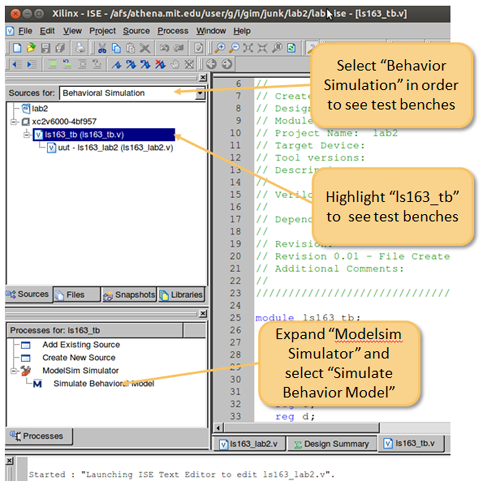
Double click on "Simulate Behavior Model". Modelsim and a Waveform window will pop up. With the mouse in the waveform window right click "Zoom Full" to view the full simulation. Simulating with Modelsim contains examples of complex test benches.
Exercise 2: Compiling and running Verilog on the labkit
In this exercise you'll design a Verilog module that reads a 4-bit value from labkit's switches and displays the appropriate hex digit on a 7-segment display.
The labkit module (defined in labkit.v) has port declarations for all the labkit peripherals as well as supplying default values for all the output ports. This is the top-level module for all labkit projects -- you should make a copy of it using a meaningful file name (eg, lab2_2.v) and modify the copy to implement the circuitry for your project. labkit.ucf (which you'll never need to modify) specifies which FPGA pin is connected to which named port in labkit.v.
Compute the appropriate value for each of segment control signals and drive them onto the appropriate FPGA output pins (I used user1[7:0]). Note that you'll have to modify or comment-out the existing line in the code that sets a default value for the output pins you're using.
Synthesize and implement your design. Generate a programming file and configure the FPGA. When your circuit is working, ask a staff member to check you off. For checkoff be prepared to show your circuit in operation, displaying different digits as the switches are turned on and off.