CHAPTER 1
Introduction
1.1 INTRODUCTION TO BASIC-5000
Welcome to MCS BASIC-52. This program was developed by INTEL as a BASIC interpreter occupying 8K of ROM using INTEL's 8052AH microcontroller. MCS BASIC-52 provides most of the features of "standard" BASICS, plus many additional features that a
pply to control environments and to the architecture of the 8052AH. Kevin Klughart ported it to the Dallas Semiconductor DS-5000. This manual is an edited and amended version of the original Intel manual.
The design goal of MCS BASIC-52 was to develop a software program that would make it easy for a hardware/software designer to interact with the DS-5000 device and include some of the real-time features of the processors as well as provide for some specifi
c I/O associated with signal processing and presentation. Klughart ported it as a tool to be used with the Harvard/MIT subject 6.121/HST575, Bioelectronics Project Laboratory. The subject is centered on modern, computer-based medical instrumen
tation. Students are responsible for implementing a complete instrument system, usually communicating with another computer functioning as a workstation and providing for control, status monitoring and data presentation. Although limited, the DS-500
0 and BASIC-5000 are a complete operating system and are representative of modern implementations where one takes advantage of features of complete systems rather than using the individual components to realize a very specific, highly optimized design.
MCS BASIC-52 offers many unique hardware and software features, including the ability to store and execute the user program out of an virtual "EPROM", the ability to process interrupts within the constructs of a BASIC program, plus an accurate real time c
lock. In addition, the arithmetic routines and I/0 routines contained in MCS BASIC-52 can be accessed with assembly language CALL routines. This feature can be used to eliminate the need for the user to write these sometimes difficult and tedi
ous programs. (NOTE: non-hardware register locations may differ in the implemented version running on the DS5000...don't depend on them...the manual is being updated and is inconsistent)
In reading this manual, you will find that some information may be repeated two or three times. The original author claims this as a feature saying "This is not an accident. Years of experience have proven that one of the most frustrating expe
riences one encounters with manuals is trying to find a particular piece of information that the reader knows is in the manual, but can't remember where." But to add balance to life, vital details are sometimes mentioned in the context of another issue e
ntirely!
1.2 GETTING STARTED
If you are like most engineers, technicians, hobbyists and humans, and don't like to read manuals, this section is for you. The purpose of this section is to get you off on the right foot. If you are in the High Anxiety Mode and just want to s
ee if the darn chip works, wire the device in the minimum hardware configuration as suggested in the Hardware Configuration chapter of this manual, apply power, and watch what happens. Perhaps nothing! You must set your communications port to 9600
BAUD, 8 bits, no parity. If you've wired things right, you will see
DS5000 Topside Basic Interpreter V2.01 20-May-1996 23:00 WITH 102.ASM EXTENSION

Ready

>
The Autobaud feature associated with the original INTEL BASIC has been removed from BASIC-5000.
1.3 WHAT HAPPENS AFTER RESET?
After RESET, MCS BASIC-52:
- Clears the INTERNAL DS5000 memory
- Initializes the internal registers and pointers
- Tests, clears, and sizes the EXTERNAL memory (locations 3000h to MTOP - nominally 5FFFh the virtual "EPROM" feature allocates external memory between 6000h and 7FFFh for stored BASIC programs)
BASIC then assigns the top of EXTERNAL RANDOM ACCESS MEMORY to the SYSTEM CONTROLVALUE - MTOP and uses this number as the random number seed. BASIC assigns the default crystal value, 11.0592 MHz, to the SYSTEM CONTROL VALUE - XTAL and uses this defa
ult value to calculate all time dependent functions, such as the PWM frequencies or the interrupt driven REAL TIME CLOCK. BASIC-5000 uses a fixed 9600 baud rate for its terminal.
- MCS BASIC-52 initializes the 8052AH's Special Function Registers TMOD and TCON to
- TCON - 244 (0F4H)
- TMOD - 32 (20H)
After Reset, the console device should display the following:
DS5000 Topside Basic Interpreter V2.01 20-May-1996 23:00 WITH 102.ASM EXTENSION

Ready

>
To see if everything is OK after Reset, type the following:
>print xtal,tcon,tmod
(BASIC should respond:)
 11059200  244  32

Ready

>
If it does, everything is working properly. If it does not, make sure that the serial port and the oscillator are connected and working. Hardware debug begins here. Verify that EA* is tied high, RST is grounded. Using an oscillosco
pe, check the clock osillator (pins 18, 19), look for activity on ALE (pin 30). You should see a burst of activity on TXD (pin 11) when BASIC-5000 sends out its initial message.
In the Appendix of this manual is a QUICK REFERENCE GUIDE. It provides a short description of all of the COMMANDS and STATEMENTS implemented in MCS BASIC-52. You might want to use this section to gain a quick understanding of the MCS BASIC-52
software package. Those of you who are familiar with the BASIC language will notice that most of the STATEMENTS and COMMANDS used in MCS BASIC-52 are "standard," so getting started should not be a problem.
1.4 DEFINITION OF TERMS
COMMANDS:
MCS BASIC-52 operates in two modes, the COMMAND or direct mode and the interpreter or RUN mode. MCS BASIC-52 Commands can only be entered when the processor is in the COMMAND or direct mode. MCS BASIC-52 takes immediate action after a command
has been entered. This document will use the terms RUN MODE and COMMAND MODE to refer to the two different modes of operation.
STATEMENTS:
A BASIC program is comprised of statements. Every statement begins with a line number, followed by the statement body, and terminated with a Carriage Return (cr), or a colon (:) in the case of multiple statements per line. Some statements can
be executed in the COMMAND MODE, others cannot. The DESCRIPTION OF STATEMENTS section of this manual describes whether a statement can be executed in the COMMAND mode or only in the RUN mode.
There are three general types of statements in MCS BASIC-52: ASSIGNMENTS, INPUT/OUTPUT, and CONTROL. The DESCRIPTION OF STATEMENT section of this manual explains what type is associated with each statement.
- EVERY line in a program must have a statement line number ranging between 0 and 65535 inclusive.
- Statement numbers are used by BASIC to order the program statements sequentially.
- In any program, a statement number can be used only once.
- Statements need not be entered in numerical order, because BASIC will automatically order them in ascending order.
- A statement may contain no more than79 characters.
- Blanks (spaces) are ignored by BASIC and BASIC automatically inserts blanks during LIST.
- More than one statement can be put on a line, if separated by a colon (:), but only one statement number is allowed per line.
FORMAT STATEMENTS:
Format Statements may only be used within the PRINT STATEMENT. The format statements include TAB([expr]), SPC([expr]), USING(special symbols), and CR (carriage return with no line feed). Details of the format statements are provided in the des
cription of the PRINT STATEMENT section of this manual.
DATA FORMAT:
The range of numbers that can be represented in MCS BASIC-52 is:
- ±1 E-127 to ± . 99999999E+127
There are eight digits of significance in MCS BASIC-52. Numbers are internally rounded to fit this precision. Numbers may be entered and displayed in four formats: integer, decimal, hexadecimal, and exponential.
EXAMPLE: 129, 34.98, OA6EH, 1.23456E+3
INTEGERS:
In MCS BASIC-52, integers are numbers that ranges from 0 to 65535 or 0FFFFH. All integers can be entered in either decimal or hexadecimal format and all hexadecimal numbers must begin with a valid digit (e.g. the number A000H must be entered 0A000H)
. When an operator, such as .AND. requires an integer, MCS BASIC-52 will truncate the fraction portion of number so it will fit the integer format. All line numbers used by MCS BASIC-52 are integers. This document will refer to integers
and line numbers, respectively in the following manner:
- [integer] - [ln num]
NOTE - Throughout this document the brackets [ ] are used only to indicate an integer, constant, etc. They are NOT entered when typing the actual number or variable.
CONSTANTS:
A constant is a real number that ranges from ± 1 E-127 to ±.99999999E+127. A constant, of course, can be an integer. This document will refer to constants in the following manner:
- [const]
OPERATORS:
An operator performs a pre-defined operation on variables and/or constants. Operators require either one or two operands. Typical two operand or dyadic operators include ADD (+), SUBTRACT (-), MULTIPLY (*), and DIVIDE (/). Operators that
require only one operand are often referred to as UNARY OPERATORS. Some typical UNARY OPERATORS are SIN, COS, and ABS.
VARIABLES:
A variable could be defined as either a letter, (i.e. A, X, I), a letter followed by a number, (i.e. Ql, T7, L3), a letter followed by a ONE DIMENSIONED expression, (i.e. J(4), G(A+6), 1(10*SIN(X))), or a letter followed by a number followed by a ONE DIME
NSIONED expression i.e. AI(8), P7(DBY(9)), W8(A+B). Variables may contain up to 8 letters or numbers including the underline character. This permits the user to use a more descriptive name for a given variable. Examples of valid variable
s are as follows:
FRED VOLTAGEI I_I1 ARRAY(ELE_1)
NOTE: DS-5000 BASIC only knows a variable by its first letter, its last letter and its length. Be careful not to name two variables such that they are indistinguishable (e.g. ART and ANT).
When using the expanded variable names available in MCS BASIC-52 it is important to note that 1) It takes longer for MCS BASIC-52 to process these expanded variable names and 2) The user may not use any keyword as part of a variable name (i.e. the variabl
es TABLE and DIET could not be used because TAB and IE are reserved words). BAD SYNTAX ERRORS will be generated if the user attempts to define a variable that contains a reserved word.
Variables that include a ONE DIMENSIONED expression [expr] are often referred to as DIMENSIONED or ARRAYED variables. Variables that only involve a letter or a letter and a number are called SCALAR variables. The details concerning DIMENSIONED
variables are covered in the description of the STATEMENT ROUTINE DIM. This document will refer to VARIABLES as: [var].
MCS BASIC-52 allocates variables in a "static" manner. That means each time a variable is used, BASIC allocates a portion of memory (8 bytes) specifically for that variable. This memory cannot be de-allocated on a variable-by-variable basis. &
nbsp;That means if you execute a statement like Q = 3, later on you cannot tell BASIC that the variable Q no longer exists so, please "free up" the 8 bytes of memory that belong to Q. Sorry, it doesn't work this way. The only way the user can
clear the memory that is allocated to variables is to execute a CLEAR STATEMENT. This Statement "frees" all memory allocated to variables.
IMPORTANT NOTE:
Relative to a dimensioned variable, it takes MCS BASIC-52 a lot less time to find a scalar variable. That's because there is no expression to evaluate in a scalar variable. So, if you want to make a program run as fast as possible, use dimensi
oned variables only when you have to. Use scalars for intermediate variables, then assign the final result to a dimensioned variable.
EXPRESSIONS:
An expression is a logical mathematical formula that involves OPERATORS (both unary and dyadic), CONSTANTS, and VARIABLES. Expressions can be simple or quite complex, i.e. 12*EXP(A)/100, H(1) + 55, or (SIN(A)*SIN(A) + COS(A)*COS(A))/2. A "stan
d alone" variable [var] or constant [const] is also considered an EXPRESSION. This document will refer to EXPRESSIONS as: [expr].
RELATIONAL EXPRESSIONS:
Relational expressions involve the operators EQUAL (=), NOT EQUAL (<>), GREATER THAN LESS THAN (<), GREATER THAN OR EQUAL TO (>=) and LESS THAN OR EQUAL TO (<=). They are used in control statements to "test" a condition (i.e. IF A < 100 THEN ...). &
nbsp;Relational expressions ALWAYS REQUIRE TWO OPERANDS. This document will refer to RELATIONAL EXPRESSIONS as: [rel expr].
SPECIAL FUNCTION OPERATORS:
Virtually all of the special function registers on the 8052AH can be accessed by using the special function operators. The exceptions are non-I/0 associated registers such as ACC, B, and PSW. Other SPECIAL FUNCTION OPERATORS are XTAL and TIME.
Details of the SPECIAL FUNCTION OPERATORS are covered in the section SPECIAL FUNCTION OPERATORS.
SYSTEM CONTROL VALUES:
The system control values include the following: LEN (which returns the length of the program), FREE (which designates how many bytes of RAM are not used that are allocated to BASIC), and MTOP (which is the last memory location that is assigned to BASIC).
Details of the system control values are covered in the section SYSTEM CONTROL VALUES.
STACK STRUCTURE:
MCS BASIC-52 reserves the first 512 bytes of EXTERNAL DATA MEMORY (starting at location 3000h in BASIC-5000) to implement two "software" stacks. These are the control stack and the arithmetic stack or ARGUMENT STACK. Understanding how the stac
ks work in BASIC-5000 is NOT NECESSARY if the user wishes only to program in BASIC. However, understanding the stack structure is necessary if the user wishes to link BASIC-5000 to ASSEMBLY language routines. The details of how to link to asse
mbly language are covered in the ASSEMBLY LANGUAGE LINKAGE section of this manual.
CONTROL STACK - The control stack occupies locations 12384 (3060H) through 12542 (3FEH) in external ram memory. This memory is used to store all information associated with loop control (i.e. DO -WHILE, DO - UNTIL, and FOR - NEXT) and basic s
ubroutines (GOSUB). The stack is initialized to 12542 (30FEh) and "grows down."
ARGUMENT STACK - The ARGUMENT STACK occupies locations 12589 (312DH) through 12798 (31FEH) in external ram memory. This stack stores all constants that MCS BASIC-52 is currently using. Operations such as ADD, SUBTRACT, MULTIPLY, and DIV
IDE always operate on the first two numbers on the ARGUMENT STACK and return the result to the ARGUMENT STACK. The argument stack is initialized to 12798 (3IFEH) and "grows down" as more values are placed on the ARGUMENT STACK. Each floating p
oint number placed on the ARGUMENT STACK requires 6 BYTES of storage.
INTERNAL STACK - The stack pointer on the 8052AH (SPECIAL FUNCTION REGISTER, SP) is initialized to 77 (4DH). The 8052AH's stack pointer "grows up" as values are placed on the stack. In MCS BASIC-52 the user has the option of placing the
8052AH's STACK POINTER anywhere (above location 77) in internal memory. The details of how to do this are covered in the ASSEMBLY LANGUAGE LINKAGE section of this manual.
LINE EDITOR:
MCS BASIC-52 contains a minimum level line editor. Once a line is entered the user may not change the line without re-typing the line. However, it is possible to delete characters while a line is in the process of being entered. This is
done by entering a RUBOUT or DELETE character (7FH). The RUBOUT character will cause the last character entered to be erased from the text input buffer. Additionally, a control-D will cause the entire line to be erased. Control-Q (X-ON)
and Control S (X-OFF) recognition occurs when using the serial port. The user is cautioned not to accidentally type a Control-S when entering information because the MCS BASIC-52 will no longer respond to the console device. Control-Q is used
to bring the console device back to life after Control-S is typed.
NOTE - In this document a carriage return is indicated by the symbol (cr). The carriage return is the RETURN key on most keyboards.
1.5 WHAT'S THE DIFFERENCE BETWEEN MCS BASIC and BASIC-5000
The DS5000 hardware and software architecture most closely resembles a CMOS 8051 microcontroller rather than the 8052 microcontroller for which MCS BASIC was developed. The 8052 has a third 16-bit timer. The DS5000 (8051) has no TIMER2 impleme
ntation. Because there is no TIMER2, the control register is not present and RCAP2 is not implemented. The DS5000 (8051) has 128 bytes of internal scratchpad RAM compared with the 8052's 256 bytes. This means that the internal stack spac
e available for subroutine calls and parameter passing is half that of the standard 8052 core. Since both the 8052 and the DS5000/8051 use this internal scratchpad RAM to save return linkages for subroutine calls, this can limit the complexity of ap
plications which make have use of subroutine nesting.
- Vectors to user routines in the program address space 2000 hex are now vectored to locations starting at 2800 hex. In the same fashion, user vectors which were placed at 4000 hex in the MCS BASIC-52 interpreter have been revectored to 2800 hex.
The support for user-written extensions to the BASIC language has been retained in this release of DS5000 BASIC.
- User RAM memory is now limited to 11775 bytes unless the bottom external memory interface is implemented. Since the whole purpose behind porting the 8052 BASIC interpreter to the DS5000 is the elimination of the external RAM/ROM interface, this
is not much of a restriction, and is in line with the overall design goals of the system.
- User RAM memory for BASIC programs and data is now based at 3000 hex instead of 0000 hex. This restriction is due to the memory management architecture in the DS5000, which manages the 32Kb of non-volatile static RAM embedded within the Soft Mic
rocontroller package.
- Support for programming of external EPROMs has been removed. The non-volatile topside memory available for user programs starts at 3000 hex and proceeds to 7FFF hex. 'ROM' space is implemented at 6000 hex within embedded DS5000 topside NVR
AM memory, giving approximately 12Kb of RAM and 8Kb of ROM space available for user programs. This partition between RAM and ROM space is currently fixed when the BASIC interpreter is assembled. It is specified by the system control variable M
TOP. Storage statements such as XBY and CAPTURE have access to all locations, including this virtual "ROM".
- The internal stack is only 128 bytes long instead of 256 bytes, so this version of the interpreter cannot support the degree of expression complexity that the 8052 could. This is not much of a restriction, and the current implementation should b
e ample for most applications.
- Undocumented author messages present in the 8052-BASIC implementation have been removed.
- The system initialization messages are different than those of 8052 BASIC.
- All error messages have been converted to lowercase for readability.
- The DS5000 will normally exit from a power-on reset condition within 2 milliseconds, which is substantially faster than the 8052 equivalent operation.
- The original 8052 BASIC only supported the PORT1 token to allow reads and writes to port P1 of the microcontroller. The DS5000 BASIC interpreter also implements ports P0, P2, and P3 with the PORT0, PORT2, and PORT3 tokens.
ROM Loader
The DS5000 includes a battery-backed 32K byte memory (called "Topside" at Dallas Semiconductor), which is allocated as program and data memory. The chip includes a loader which can download a program using the serial port or when the DS5000 is plugg
ed into a special parallel loader circuit. BASIC-5000 was loaded serially, using this feature. It is not intended that additional external memory, either as RAM, ROM, or EPROM will be used with this system. The extended BASIC-5000 statem
ent HEXLOAD supports loading programs in the user space 3000H to 7FFFH.
Power-Fail
The DS5000 includes power-level detection and an interrupt that potentially allow "safe" egress upon a power failure. This feature is currently disabled in BASIC-5000.
WatchDogTimer
The DS5000 implements a watchdog timer which is activated on MCU power-up and must be satisfied by periodic writes to a special function register (or it must be disabled). The purpose of this "watchdog" is to detect some types of software errors by
forcing a reset of the processor. The reset procedure is more complex than a simple register access and is unlikely to occur by accident. This is not currently activated in BASIC-5000.
Real-Time Clock
The DS5000T units include a battery-backed hardware real-time clock and calendar. Extended BASIC-5000 provides RTCGET and RTCSET statements to access to the features of the Real-Time Clock. It is a reliable basis for logging events and comparison wi
th the software real-time clock allows discovery of crashes and system-resets.
Graphics Statements
Extended BASIC-5000 includes several commands for communicating with a Tektronix 4010-series graphics terminal. They include CLS, DRAW, LINE, MOVE, QUIT and TEK. The popular public-domain KERMIT terminal emulator includes these graphics capabi
lities. The TEK command is unique and draws a set of samples as a waveform.
Data Acquisition Statements
An analog-to-digital converter, such as the National Semiconductor's ADC0848, can be interfaced to the DS-5000. The statements SAMP, MEASURE, CAPTURE, and EVENT provide access to analog data and real-time events. COPY and DUMP allow rapid relo
cation or transferal of real-time data. These are primitive resources allowing single and fixed rate (200 samples/second) sampling.
Unusual features
The IF-THEN ELSE STATEMENT when used with multiple statements per line functions differently than when used in single-statement lines
EXAMPLE 1:
10 IF A=B THEN C=A : A=A/2 : GOTO 100

20 PRINT A
EXAMPLE 2:
10 IF A=B THEN C=A

12 A=A/2

14 GOTO 100

20 PRINT A
BASIC-5000 executes the remainder of the line if and only if the test A = B proves to be true. This means in EXAMPLE 1 IF A did equal B, it would then set C = A, then set A = A/2, then execute line 100. IF A did not equal B, it would then PRIN
T A and ignore the statements C = A : A = A/2 : GOTO I 00. In EXAMPLE 2 C=A will execute only if the equality A=B is met. Line 12 will execute regardless. This same logical interpretation holds true for the ELSE statement as well.
Some consider this more useful because fewer GOTO statements need be employed in a typical program.
Other unusual features of BASIC-5000
- X-ON (control Q) and X-OFF (control S) are implemented. These permit the user to "stop" (control S) and start (control Q) the display of characters during a LIST or PRINT. This feature also permits synchronization with external 1/0 (input/
output) devices. The X-OFF (control S) functions on a line by line basis, not on a character by character basis.
- Five non-standard statements have been added. These include IDLE, LD@, ST@, PROG, and RROM. Details of these statements are listed under the DESCRIPTION OF STATEMENTS section of this manual.
- A RUN TRAP option has been provided. This option traps the BASIC-5000 in the program RUN mode and will not permit the user to exit this mode (control-C is disabled). A special-purpose application can thus be implemented and the user res
tricted to running only this application.
- A user STATEMENT/COMMAND expansion option has been provided. This permits the user to easily add new or custom STATEMENTS and COMMANDS to MCS BASIC-52.
- A number of new assembly language user OP BYTES have been added. These permit the user to make better use of the STATEMENT/COMMAND expansion option previously described.
- A new variation on the PRINT (including PH0. and PH1.) and LIST statements have been added. This new option is evoked with an @ character (EXAMPLE: PRINT@ or LIST@) and permits the user to write specific output drivers for these statements an
d commands. When the @ PRINT or LIST is evoked, MCS BASIC-52 CALLS external code memory location 2A3CH. The user must put the specific output driver in this location. More details of this option are in Description of Statements section o
f this manual.
- The control stack has been made more "forgiving." This means that the user can execute a GOSUB to a subroutine that contains a FOR-NEXT loop and return from the subroutine without completing the FOR-NEXT loop.
- The question mark character ? is interpreted as a PRINT statement (EXAMPLE: (PRINT 10 + 20 is the same as ? 10 + 20). The symbol P. remains a shorthand notation for PRINT.
- The FOR-NEXT statement can be executed in the direct mode. This lets the user write short routines in the DIRECT MODE to, for example, display a region of memory (EXAMPLE: FOR I=200H to 210H: PH0. XBY(I): NEXT I).
- Variables can be up to 8 characters in length, however, only the first character, the last character, and the total number of characters are of signifance. This lets the user better describe variables that are used in a program. But als
o note that F1234J = F3456J = FOOL_J. Don't be fooled!
- The FOR-TO-{STEP}-NEXT statement can be executed in the COMMAND MODE of MCS BASIC-52. Additionally, the NEXT statement does not require a variable. Details of these features are covered in the Description of Statements section of this m
anual.
- The REM statement can be executed in the COMMAND MODE. If the user is employing some type of UPLOAD/DOWNLOAD routine with a computer, this lets the user insert REM statements without line numbers in the text and not download them to the MCS B
ASIC-52 device. This helps to conserve memory.
Memory Changes
Several changes in memory allocations are summarized in the following external memory map for the DS5000T:
Revised DS5000T BASIC Memory Map
| DS5000 BASIC INTERPRETER - 10 KB |
0000H ~ 2400H |
| 6121J COMMAND EXTENSION VECTORS |
2800H - 28FFH |
| 6121J COMMAND EXTENSION CODE |
2900H - 2FFFH |
| COMMAND LINE STORAGE |
3000H - 30FFH |
| BASIC INTERPRETER INTERNAL VARIABLES |
3100H - 31FFH |
| EVENT QUEUE |
3200H - 32FFH |
| BASIC PROGRAM STORAGE |
3300H- |
| BASIC VARIABLE STORAGE |
- 5FFFH |
| SIMULATED ROM STORAGE - 8KB |
6000H - 7FFFH |
| OFF-CHIP EXTERNAL RAM ADDRESSING - 32KB |
8000H - FFFFH |
In addition to the internal MCU RAM locations reserved by the MCS BASIC-52 interpreter, the DS5000/BASIC implementation reserves internal RAM location 7Fh to perform memory management functions. Users should not modify this memory location under any
circumstances.
Internal MCU RAM locations 70h-7Eh are used by the 6.12IJ/HST570 extensions for local variable storage. The functions of these reserved locations is given in the following table:
| Internal RAM Address
| Function |
| 70h
| Timer count (millisecond) for current sample.
|
| 71h
| Timer count (low byte) for current sample.
|
| 72h
| Timer count (high byte) for current sample
|
|
|
| 73h
| Unused - reserved for future use
|
|
|
| 74h
| Timer count (millisecond) for last interrupt 1event
|
| 75h
| Timer count (low byte) for last interrupt 1 event
|
| 76h
| Timer count (high byte) for last interrupt 1 event
|
|
|
| 77h
| Last TEK MOVE X address (low byte)
|
| 78h
| Last TEK MOVE X address (high byte)
|
| 79h
| Last TEK MOVE Y address (low byte)
|
| 7Ah
| Last TEK MOVE Y address (high byte)
|
|
|
| 7Bh
| QUEUE_DPL address of CAPTURE queue structure (low byte). This structure contains a pointer to the actual queue structure created by the CAPTURE command.
|
| 7Ch
| QUEUE DPH address of CAPTURE queue structure (high byte). This structure contains a pointer to the actual queue structure created by the CAPTURE command.
|
|
|
| 7Dh
| QUEUE_SPL Queue offset of last INTI event sample (low byte). This structure contains the offset into the queue structure corresponding to the last INTI event which was sampled. Note that this is an offset, not an absolute address.
This offset may be added to the base queue address QUEU_DPL above to obtain the absolute data sample address.
|
| 7Eh
| QUEUE_SPR Queue offset of last INTI event sample (high byte). This structure contains the offset into the queue structure corresponding to the last INTI event which was sampled. Note that this is an offset, not an absolute address.
;This offset must be added to the base queue address QUEUE_DPH above to obtain the absolute dataI sample address.
|
|
|
| 7Fh
| Used by BASIC interpreter to preserve PORT 2 load value for simulation of page mode extemal memory addressing to topside DS5000 memory.
|
Serial Port Note
The DS-5000 BASIC interpreter defaults to a 9600 baud serial port interface on power up. This serial port interface is somewhat robust in its ability to accept a variety of interfaces, which may not adhere completely to the EIA-232C interface.
;Rise times and bit-timing are particularly important for the software within the DS-5000 Loader ROM. Unlike the BASIC interpreter, the loader does not assume a fixed baud rate for the serial port. The ROM loader performs an auto-bauding seque
nce based on what it assumes will be a carriage return (CR) sequence from the serial interface. If the rise times of the EIA-232C interface are not to specification or the bit timings are out of specification, the DS5000 may refuse to communicate wi
th the Dallas Semiconductor development KIT or the included SMTK loader software. It is therefore strongly advised that only an interface meeting EIA-232C specifications be used with the DS5000 when attempting to load the BASIC interpreter and 6121J
extension modules.
BASIC floating point opcode values changes
Several of the BASIC opcodes for the floating point subsystem were changed in this release of DS50OO/BASIC. This information was not documented in either the user manual the thesis "Porting MCS BASIC-52 Interpreter to the DS5000 Soft Microcontroller
." The conversion from original MCS BASIC-52 to the new implementation is as follows:
| Old |
New |
Function |
| 81h
| 81h
| Input an ASCII floating point number
|
| 82h
| 82h
| Floating point addition
|
| 84h
| 85h
| Floating point subtraction
|
| 86h
| 88h
| Floating point comparison
|
| 88h
| 8Bh
| Floating point multiplication
|
| 8Ah
| 8Eh
| Floating point division
|
| 8Cb
| 91h
| Hexadecimal input scan
|
| 8Eh
| 94h
| Input floating point number
|
| 90h
| 97h
| Output floating point number
|
| 92h
| 9Ah
| Binary-to-ASCII conversion
|
| 94h
| 9Dh
| ASCII-to-Binary conversion
|
| 96h
| A0h
| Multiply floating point number by 10
|
| 98h
| A3h
| Output R3:Rl to the console in hexadecimal
|
| 9Ah
| A6h
| Push R2:R0 on argument stack
|
System power requirements
Neither the thesis document nor the user manual mentions the voltage and current requirements of the DS5000. Since the DS5000 is fabricated with full CMOS technology, it may be operated on a 6-volt battery power supply. It must be powered by 5
.0 Volts ± .25 to be TTL-compatible. And notice that some other devices (notably charge-pump power converters such as that in the MAX232 or DS1228) have absolute upper voltage limits of 6.0 volts. The following table details the power require
ments of a DS5000 system running with an 11059200 Hz crystal with and without the addition of the DS1228 RS-232 serial interface.
DS5000 Current Versus Operating Mode
| Mode
| Ic (mA) @ Vcc = 5 V
(With/Without DS1228)
| Ic (mA) @ Vcc = 6 V
(With/Without DS1228)
|
| RESET
| 18/17
| 25/23
|
| Active
| 24/24
| 33/32
|
When the BASIC-5000 statement IDLE is executed, power is reduced substantially to in the order of 6 mA depending on the frequency of interrupts.
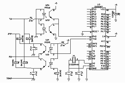
Sample Minimal System Schematic
The schematic below shows a minimal set-up for the DS-5000 connected to a serial device through optical isolators.