
BASIC-5000 has been extended to include real-time analog-to-digital data acquisition, high-speed event resolution, Tektronix graphics display capability, and access to the embedded real-time clock (RTC) present in the DS5000T Soft Microcontroller.
Data Acquisition Commands
Real-time Clock/Calendar Command (DS5000T Only)
These commands provide access to the battery-backed real-time clock contained in the DS5000T.
Tektronix 4010 Graphics Commands
MODE: RUN
TYPE: INPUT/OUTPUT
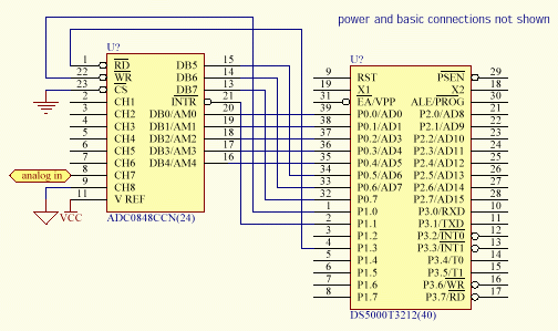
Initiates a single A-D conversion using an external analog-digital converter connected to PORT0, waits for a conversion completion signal on PORT1.1, and places the 8-bit result on the argument stack. The multiplexer address [mar] refers to one of 2 3 input channel combinations on the ADC0848. See the ADC0848 datasheet for more info. It is required even if a different ADC is used. This address is left unchanged after execution, so SAMP can be used to select an address for use with M EASURE or CAPTURE. Time of conversion is stored in locations 70h, 71h, and 72h (5 milliseconds, lsbyte, msbyte respectively).
EXAMPLE:
10	SAMP(01Eh)

20	POP VALUE

30	PH0. VALUE
This example performs an analog-to-digital conversion, places the result in the BASIC variable VALUE, and prints it as a hexadecimal number ranging from 0 < value < 0FFH (0 < value < 255). The [mar] of 1Eh corresponds to a pseudo-differe ntial mode with channel 7 as the + input and channel 8 as the - input.
The DS5000 first sets PORT0 = [mar], with P1.3 (ADC_READ high). It then generates a single, low 2 microsecond pulse on P1.0 (ADC_WRITE) to load [mar] and start a conversion. P1.1 examines the status (interupt) level and waits for the line to b e low. When P1.1 goes low, the DS5000 generates a low on P1.3 (ADC-READ) and pushes the value on PORT0 onto the argument stack. For converters that do not provide this signal, P1.1 must be tied to "low" and the statement will acquire the value on the converter output when the conversion is initiated. The AD670 is a single-channel converter with programmable FORMAT and RANGE (UPO/BPO). These can be hard-wired.
Below is a timing diagram of the control signals for a conversion
Note: The ADC0848 must be connected to the DS5000 as follows.
MODE: RUN
TYPE: INPUT/OUTPUT
Places the time the statement was executed on the argument stack, initiates a single A-D conversion using an external analog-digital converter, waits for "low" on P1.1 (does not look for transition), and places the 8-bit result on the argument stack. &nbs p;The time of conversion is stored in locations 70h, 71h, and 72h (5 milliseconds, lsbyte, msbyte respectively). This is the same as AD670 with the addition of the time measurement. Interface requirements and channel/mode selections are the s ame as AD670.
EXAMPLE:
10 	CLOCK 1

20	MEASURE

30	POP MTIM

40	POP MVAL

50	PRINT MTIM, : PH0. MVAL
This example performs an analog-to-digital conversion and places the sample time in the BASIC variable MTIM and the measured result in the BASIC variable MVAL. The MTIM BASIC time result is in the range 0.0 to 65535.995 seconds and corresponds to th e TIME variable in BASIC at the time the AD670 sample measurement was made. The binary measured result MVAL is treated as an unsigned integer in the range 0-255. Note that the BASIC CLOCK must be operating for the time value to be correct. &nb sp;This is done by the CLOCK1 statement in line 10.
STATEMENT: CAPTURE [Q_addr],[Q_size]
MODE: RUN
TYPE: INPUT/OUTPUT
Continuously captures data samples from the external analog-to-digital converter and places the results in a circular queue. Stores current time and queue pointer in queue header with each sample. [Q_addr] is the starting address of the queue structure to be built and must be in middle of 3300H to 5FFFH range. [Q_size] is the size in bytes of the queue structure to be built.
The CAPTURE statement extension to BASIC creates a circular queue at the specified [Q_addr] which is [Q_size] long and then enables sampling of the external analog-digital converter at 5 millisecond intervals. See AD670 statement for interface speci fications. Each sample is placed in the circular queue and may be accessed by the foreground BASIC program at any time. The DUMP and TEK statements provide a mechanism of transferring this circular queue data to display devices. Current time and queue pointer value are stored when an event occurs on INT1. The time and queue pointer of events are stored in locations 74h,75h and 76h (5 msec, lsbyte, msbyte of time) 7Dh and 7Eh (lsbyte and msbyte of queue pointer). Statement EVE NT gets event time and queue pointer value and pushes it onto the stack. P1.1 can be examined for a logical-low indicating when a conversion has been completed. If a low conversion-complete signal is not available, P1.1 must be tied low.
EXAMPLE:
10	CAPTURE 5000H,250

20	CAPTURE
BUG NOTICE: [Q_size] may not be integer multiples of 256 (100H)
On line 10 the example creates a queue structure of 250 bytes starting at address 5000H. This queue contains (250-4=446) bytes of sampled data and 4 bytes of control information. The example in line 20 terminates data capturing operations on t he specified Queue. The contents of the queue are not affected by this "stop-capturing" instruction and the data may be examined, transferred, and otherwise manipulated, but the capturing operation cannot be resumed. A new queue must be create d which will initialize the data-space to zero.
The queue structure created by the CAPTURE statement contains a 4-byte control header. The first two bytes of this header (lo,hi) contain the size of the queue in bytes. The next two bytes in the queue control header (lo, hi) point to the loca tion of the newest data in the circular queue. The circular buffer contains the recent history of the input data ([Q_size] x 5 msec), so 1000 samples would represent the most recent 5 seconds of data. The queue pointer specifies the location o f the oldest sample (the next byte to be written or first byte to be read, depending on the operation, this same queue structure is used in the data presentation statements TEK and DUMP, which read the data.)
Consider a sampling process where we begin at t0 and take samples at t0, t1, t2,...,ti, ti+1, ti+2, ....
Initially the queue contains the value 0 where data will be placed (locations 5004H to 5000H + 250 or 5004H to 50FAH). At t0+, the first sample is stored in location 5004H. At t5+, the first 6 samples have been stored at locations 5004H throug h 5009H and the pointer is specifying 500AH as the next location to store sample X6 when it arrives. At t250+, the buffer has filled completely once plus four (it has 246 locations and 250 samples have been taken, so the oldest data, sample X0 has b een replaced by X246, the next oldest by X247, and so-on). Sample X249 (the 250th sample) has been stored in 5007H and the pointer is specifying location 5008H to store X250. At t1000, the buffer has filled more than 4 times. Specificall y 4x246 + 17 samples have been acquired and stored. The first location, 5004h contained sample X0, which was replaced by X246, X738, and now contains X984. Sample X1001 will be placed in 1001-984 +5004H = 5015H which contains X754...the oldest remai ning sample. The queue provides the recent history of the data...the last 246 samples. Where it is stored is relevant to how you plan on accessing it. TEK and DUMP reorder the data, presenting the oldest first.
Contents of Queue
	   	   Memory location
		   t=0-
		   t=0+
		   t=5+
		   t=250+
		   t=1000+


	   	   5000H
		   0FAH
		   0FAH
		   0FAH
		   0FAH
		   0FAH


	   	   5001H
		   00
		   00
		   00
		   00
		   00


	   	   5002H
		   04
		   05
		   0AH
		   08
		   14H


	   	   5003H
		   00
		   00
		   00
		   00
		   00


	   	   5004H
		   00
		   X0
		   X0
		   X246
		   X984


	   	   5005H
		   00
		   00
		   X1
		   X247
		   X985


	   	      .


	   	   5007H
		   00
		   00
		   X3
		   X249
		   X987


	   	   5008H
		   00
		   00
		   X4
		   X4
		   X988


	   	   5009H
		   00
		   00
		   X5
		   X5
		   X989


	   	   500AH
		   00
		   00
		   00
		   X6
		   X990


	   	   500BH
		   00
		   00
		   00
		   X7
		   X991


	   	      .


	   	      .


	   	   5014H
		   00
		   00
		   00
		   X12
		   X1000


	   	   5015H
		   00
		   00
		   00
		   X13
		   X754


	   	   5016H
		   00
		   00
		   00
		   X14
		   X755


	   	      .


	   	      .


	   	   50F9H
		   00
		   00
		   00
		   X244
		   X982


	   	   50FAH
		   00
		   00
		   00
		   X245
		   X983
MODE: RUN
TYPE: INPUT/OUTPUT
Returns to the stack the time of the last INT1 event and the queue offset pointing to the location of the sample stored by CAPTURE when the event occurred. This allows the programmer to deduce when a significant event occurred in the data stream and also where to look for that event in the circular queue generated by a prior CAPTURE statement. Typically the event is "marked" by displacing it vertically.
EXAMPLE:
10  ONEX1 100

20  CAPTURE 5000h, 1000

30  FLAG=0

40  IF (FLAG=0) GOTO 40

50  EVENT

60  POP ETIM

70  POP EQUE

80  PRINT "Event time =",ETIM,"; Event queue index=",EQUE

90  GOTO 30

100	FLAG=1

110	RETI
The example at line 10 initializes external interrupt 1 processing within the BASIC interpreter. The example at line 20 creates a queue structure of 1000 bytes starting at address 5000H. Note that this queue contains (1000-4=996) bytes of user data and 4 bytes of control overhead. It is important to note the ordering of the ONEX1and CAPTURE statements, as the ONEX1 statement if used in the program must always precede the use of the CAPTURE statement. Line 30 initializes a foregroun d flag, which is used to detect the occurrence of an INT1 interrupt event. This event is sampled in line 40 and when the event is detected, the statements from line 50-90 are executed by the BASIC interpreter.
The description of the CAPTURE statement provides a discussion of the queue structure that is generated by this example. The EVENT statement may not be placed in any BASIC statement sequence that is called by an interrupt sequence such as ONEX1 or O NTIME. This restriction is required because the EVENT statement uses floating point arithmetic, which is restricted to non-interrupt program threads within the BASIC interpreter. The preceding example allows a foreground task to perform the pr ocessing necessary to simulate execution of the EVENT statement within the interrupt context.
MODE: COMMAND/ RUN
TYPE: INPUT/OUTPUT
Reads a peripheral device's output connected to PORT0, addressed by PORT2, strobed by RD*. [addr] is the 8-bit address presented on PORT2 used to select a device. A low signal is generated on P3.7 (RD*) and the value of PORT0 is read. P3 .7 (RD*) returns high and the input value on PORT0 is pushed onto the argument stack.
EXAMPLE:
10  IOIN(0FEh)

20  POP VAL

30  PH0. VAL
PORT2 outputs 11111110 to select an input device. The value on PORT0 is pushed onto the stack. This value is then popped and printed in hexadecimal.
A timing diagram is shown below.

MODE: COMMAND/ RUN
TYPE: INPUT/OUTPUT
Loads a peripheral device's input connected to PORT0, addressed by PORT2, strobed by WR*. [addr] is the 8-bit address presented on PORT2 used to select a device. PORT0 takes the value from the top of the argument stack and a low signal is gene rated by P3.6 (WR*). The data is then loaded by the peripheral and P3.6 (WR*) returns high.
EXAMPLE:
10	POP VAL

20	IOOUT(0FDh)
VAL is pushed onto the stack. PORT2 outputs 11111101 to select an output device. WR* strobes the device to signal data ready to be loaded.
A timing diagram is shown below.

MODE: COMMAND/ RUN
TYPE: INPUT/OUTPUT
The CLS extension to BASIC sends the control character to enter the graphics mode and then clears the screen and places the cursor at the upper-left corner of the screen in a display controlled by the Tektronix 4010 graphics language. This statement appears like the DOS CLS command.
MODE: (COMMAND)/RUN
TYPE: INPUT/OUTPUT
The DRAW statement draws a line from the current cursor position, established by a MOVE or a previous DRAW statement to the coordinate specified in the argument. Allowable ranges are 0,0 to 1023,1023 which correspond to the lower left (0,0) and the upper right (1023, 1023) corner of the screen. Both arguments are required and each argument may evaluate to any valid BASIC integer expression. The statement evaluates the arguments modulo 1023.
EXAMPLE:
10	MOVE  0,0

20	DRAW  9,0

30	DRAW  9,9

40	DRAW  0,9

50	DRAW 0,0

60 	QUIT
This example draws a square box 10 units by 10 units. The lower-left corner of the box is at the lower left corner of the screen.
Depending on the graphics display being used the displayable limits for X and Y may be smaller than 1023 x 1023. KERMIT seems to provide 1023 x 1023 virtual pixels with a 1078 X 768 pixel real display. The DRAW statement is only valid after th e MOVE command has been issued. The DRAW and LINE statements are only valid between a MOVE-QUIT command block.
MODE: (COMMAND)/RUN
TYPE: INPUT/OUTPUT
Selects a line type for the Tektronix 4010 DRAW command. LINE must be delimited by a MOVE-QUIT block. Types are shown:

EXAMPLE:
10	CLS

20	FOR I=1 TO 8

30	MOVE 0, 50*I:LINE I:DRAW 200,50*I:QUIT:PRINT I

40	NEXT I

50 	MOVE 0, 1000
The example is printed to the right. PRINT occurs where the graphics cursor was after quit. MOVE 0, 1000 puts the cursor at the top of the screen, so the > prompt does not appear in the captured screen.
STATEMENT: COPY [source_addr],[dest_addr],[count]
MODE: COMMAND/RUN
TYPE: INPUT/OUTPUT
Copies a block of data memory starting at [source_addr] of length [count] bytes to a specified target address [dest_addr]. Note that no address translation occurs in the source and destination address values. They are treated as absolute quant ities. All three arguments are required and each argument may evaluate to any valid BASIC integer expression. The valid range of each argument is 0-65535. If the count argument is zero, then no data bytes will be transferred. This function may be used to operate on DS5000 topside as well as external (bottom-side) memory. Provision is made within this function to correctly process overlapping source and destination memory blocks.
EXAMPLE:
10 COPY 5000h,5400h,1024
This example transfers 1024 bytes from source address 5000 hexadecimal to target address 5400 hexadecimal.
MODE: COMMAND/RUN
TYPE: INPUT/OUTPUT
Terminates a Tektronix 4010 line drawing (graphics) sequence which have been issued by MOVE, DRAW, or TEK and sends a carriage return (20H) to the terminal. Leaves alphanumeric cursor in current location if display remains in graphics mode. Ea ch segment of a drawing must end with a QUIT.
EXAMPLE:
10	MOVE 0,0

20	DRAW 9,0

30	DRAW 9,9

40	DRAW 0,9

50	DRAW 0,0

60	QUIT
This example draws a box with side lengths of 10 units with the lower left-hand corner at the origin 0,0. The QUIT statement in line 60 terminates the final DRAW command in line 50. Displaying a carriage return on the Tektronix 4010 display is equivalent to issuing the QUIT statement.
STATEMENT: DUMP [Q_addr],[count]
MODE: COMMAND/RUN
TYPE: INPUT/OUTPUT
The DUMP extension to BASIC transmits [count] bytes of information in the specified queue beginning at [Q_addr] to the serial port of the DS5000 starting with the oldest data. This allows, for example, PC-based applications to retrieve data from the DS5000 after it has captured it in a background queue structure.
The DUMP statement only operates on a circular queue structure created by the CAPTURE command. Note also that the length of the data area in such a queue will be the size of the queue minus 4 bytes of queue overhead. Thus, in the example below , there is only 996 bytes of useful data in the queue. Byte counts greater than the total number of data bytes in the queue will wrap and data will be repeated.
EXAMPLE:
10	CAPTURE 5000h,1000

20	(other BASIC statements)

30	CAPTURE

40	DUMP 5000h,100
This example enables data capturing and creates a circular queue at address 5000 hexadecimal in line 10. The background data capture operation begins and is later stopped in line 30. The captured queue data (the first 100 bytes starting with t he oldest) is then transferred in binary format to the DS5000 serial port in line 40.
MODE: COMMAND/RUN
TYPE: INPUT/OUTPUT
The MOVE extension to BASIC repositions the Tektronix graphics cursor to a new screen position. The display is not modified during this operation, the current graphics cursor position is just moved. A subsequent DRAW command will generate line vectors from this new display coordinate. A PRINT command will print beginning at the location specified by the last MOVE, DRAW, or TEK graphics command. Both arguments are required and each argument may evaluate to any valid BASIC integer ex pression. The valid range for [X] and [Y] is 0 - 1023. Depending on the graphics display adapter being used, the displayable limits for [X] and [Y] may be considerably smaller than the Tektronix 4010 restriction of 0-1023.
EXAMPLE:
10	MOVE 0,0

20	DRAW 9,0

30	DRAW 9,9

40	DRAW 0,9

50	DRAW 0,0

60	QUIT

70	PRINT "foo"
This example draws a box with side lengths of 10 units with the lower left-hand corner at the origin (0,0). The MOVE statement in line 10 initially positions the graphics cursor at the box origin of (0,0) before drawing any line vectors.
STATEMENT: RTCGET [time_index]
MODE: COMMAND
TYPE: INPUT/OUTPUT
The RTCGET extension to BASIC allows the current date/time to be read from the real-time clock (RTC), which is embedded in the DS5000T. The value is stored in the argument stack. The RTC contains 8 bytes of BCD-encoded time information describ ed in the table below. Direct mode is not allowed with this statement.
The [time_index] argument is required and may evaluate to any valid BASIC integer expression. The [time_index] argument must evaluate to an integer 0-7. The value returned on the stack will be a positive number 00-99. The return value wi ll always be zero if the RTC is not present or the host CPU is a DS5000.
	   	   Time Index
		   Part of Time
		   Range


	   	   0
		   centi-seconds
		   00-99


	   	   1
		   seconds
		   00-59


	   	   2
		   minutes
		   00-59


	   	   3
		   hours
		   00-23


	   	   4
		   day-of-week
		   00-07
(Sunday = 0)


	   	   5
		   day-of-month
		   01-31


	   	   6
		   month
		   00-12


	   	   7
		   year
		   00-99
EXAMPLE:
10	RTCGET 7
20	POP YEAR
This example gets RTC register 7 (current year) and places it in the BASIC variable YEAR. Note that the value returned will be in the range 00-99.
Reference the RTCSET statement for information regarding the initial calibration procedure for the DS5000T real-time clock.
STATEMENT: RTCSET [time_index],[time_value]
MODE: COMMAND
TYPE: INPUT/OUTPUT
The RTCSET extension to BASIC allows the real-time clock (RTC), which is embedded in the DS5000T to be set to any date and time. The RTC contains 8 bytes of BCD-encoded time information as illustrated in the table below. Both arguments are req uired and each argument may evaluate to any valid BASIC integer expression. The [time_index] must evaluate to an integer between 0 and 7. The [time_value] argument range depends on the value of the [time_index] but in no case may be less than 0 or g reater than 99.
	   	   Time Index
		   Part of Time
		   Range


	   	   0
		   centi-seconds
		   00-99


	   	   1
		   seconds
		   00-59


	   	   2
		   minutes
		   00-59


	   	   3
		   hours
		   00-23


	   	   4
		   day-of-week
		   00-07
(Sunday = 0)


	   	   5
		   day-of-month
		   01-31


	   	   6
		   month
		   00-12


	   	   7
		   year
		   00-99
The RTCSET statement must be invoked 8 times to properly configure the RTC in the DS5000T with the correct date and time. Once this procedure is accomplished, the RTC will maintain an accurate date/time value to within approximately 1 minute/month i n the absence of system power.
The Real-time clock operates on a scale of seconds to years and is battery-backed. It can be used in combination with the TIME variable in BASIC-5000 to detect crashes and power-failures by a routine that resolves the two independently determined va lues of time.
EXAMPLE:
10 RTCSET 3, 18
This example sets RTC register 3 (hours) to 18. This corresponds to setting the current hour to 6 PM.
STATEMENT: TEK [Q_addr],[count]
MODE: COMMAND/RUN
TYPE: INPUT/OUTPUT
The TEK extension to BASIC takes [count] bytes of information in the specified queue structure beginning at [Q_addr] and transfers it to the serial port of the DS5000 in Tektronix 4010 format starting with the oldest data at the left. TEK should be embedded between a MOVE-QUIT block. Data is presented as an offset to the origin established by the graphics cursor. The vertical "deflection" of this display directly maps the unsigned binary number (0 -255) as height in pixels.
EXAMPLE:
10	CAPTURE 5000h,1000

20	(other BASIC stateements)

30	CAPTURE

38	MOVE 200,300

40	TEK 5000h,100

42	QUIT
This example enables data capturing and creates a circular queue at address 5000H hexadecimal in line 10. The CLOCK must be running. The background data capture operation begins and is later stopped in line 30. The captured queue data (t he oldest 96 bytes) is then plotted using Tektronix 4010 format via the DS5000 serial port in line 40. The plot will begin at x=200, y=300 + oldest sample and end at x=300 y=300 + 96th oldest sample.
The TEK statement operates on a circular queue structure created by the CAPTURE command. Note also that the length of the data area in such a queue will be the size of the queue minus 4 bytes of queue overhead. Thus, in the example above, ther e are only 996 bytes of useful data in the queue. Byte counts greater than the total number of data bytes in the queue will generate duplicate output data due to queue wraparound. The TEK statement can be used to present other data as a wavefo rm by creating an appropriate queue structure. The first two bytes contain the size of the queue (low, high bytes) followed by the pointer (low, high) indicating the location of the oldest data, which will be displayed first.
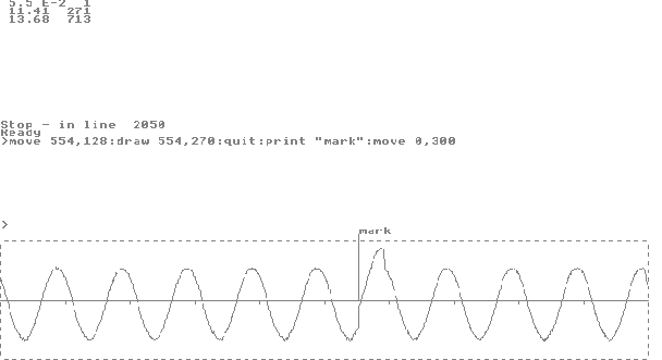
The display illustrating BASIC-5000 graphics commands is a clip-board capture of the full screen display produced by KERMIT 3.14 emulating a Tektronix 4010 graphics terminal. The figures at the top of the screen, 11.41, 271 are the time and Q_pointe r value when a positive voltage step was superposed on the 2-Hz sinusoid being captured. A logical "low" signal was presented to INT1 with the leading edge of the step causing an interrupt. The second pair, 13.68, 713 are the approximate time and the Q_pointer value when the CAPTURE operation was terminated. The marker was placed at 554 = (1000-713) + (271-4), which corresponds to the distance from the oldest data to the end of the data space (1000-713) plus the distance from the beginni ng of the data space to the marked event (271-4). The time 13.68 results from executing line 1025 and is thus later than the last sample time. The actual time of the last sample is stored in locations 70H, 71H, and 72H, which would allow inde xing by time rather than Q_pointer. The actual time of the last sample was 13.615 rather than 13.680. Using 13.615 - 11.410 = 2.205. The event occurred 2.205 seconds after the queue stopped. 2.205/.005 = 441 samples went by. The newest sample is 996 - 1 from the oldest so the marker would go at 995 - 441 = 554.
Program parameter A is a time-waste-loop. Parameter B determines how many "events" will be examined. Because the statement EVENT cannot be used within an interrupt, the interrupts are effectively "off" during execution of the TEK statement, wh ich takes a lot of time. A superior alternative might be to access the time and pointer information directly.
1	DIM ETIM(10),EQUE(10)

2     K=1

5     A=10

6     B=1

7     CLOCK 1

8	PRINT "running E_MARK1.BAS stored in ROM"

10	GOSUB 200

12	ETIM(0)=TIME

14	EQUE(0)=1

20	FOR I=0 TO A :  NEXT I

25	ONEX1 500

29	CAPTURE 5000H,1000

34	FLAG=0

40	FOR J=0 TO 50 : NEXT J

44	CLS

45	GOSUB 300

46	GOSUB 400

48	MOVE 0,0

50	TEK 5000H,1000

60	IF (FLAG=0) GOTO 40

70	EVENT

72	POP ETIM(K)

74	POP EQUE(K)

76	K=K+1

78	IF K>B GOTO 1000

200	PORT1=3

210	PORT0=1DH

220	PORT1=7

230	PORT1=6

240	PORT1=7

245	PORT0=0FFH

250	PORT1=3

260	RETURN


300	MOVE 0,0

303	LINE 3

310	DRAW 0,256

320	DRAW 1000,256

330	DRAW 1000,0

340	DRAW 0,0

343	LINE 1

350	RETURN

400	MOVE 0,128

410	DRAW 1000,128

415	FOR I=100 TO 900 STEP 100

420	MOVE I,128

421	DRAW I,120

430	NEXT I

460	RETURN

500	FLAG=1

510	RETI

1000	CAPTURE

1006	MOVE 0,700 : QUIT

1007	CLS

1008	FOR K=0 TO B

1010	PRINT ETIM(K),EQUE(K)

1020	NEXT K

1025	PRINT TIME, XBY(5003H)*256+XBY(5002H)

1030	QUIT

2000	GOSUB 300

2010	GOSUB 400

2020	MOVE 0,0 : TEK 5000H,1000

2030	MOVE 0,500 : QUIT

2050	STOP