Welcome to the MIT Gas Turbine Laboratory
About the MIT Gas Turbine Laboratory
The Gas Turbine Laboratory participates in research topics related to short, mid and long-term problems, and maintains strong ties with industry and government research in the areas of power, propulsion, and turbomachinery technology.
Our Mission
To advance the state-of-the-art in aerospace power and propulsion by creating impactful solutions important to society with emphasis on innovative, novel, and transformative approaches.

History of the GTL

Early Gas Turbine History

Research
The GTL has had a worldwide reputation for research and teaching at the forefront of gas turbine technology for over 50 years. The lab is a reflection of the shared interest of its faculty and staff in both working at the frontiers of aeropropulsion and educating graduate students in this technology. We work in this area because we find it rewarding and exciting, and hope that we can transmit this excitement during your stay.
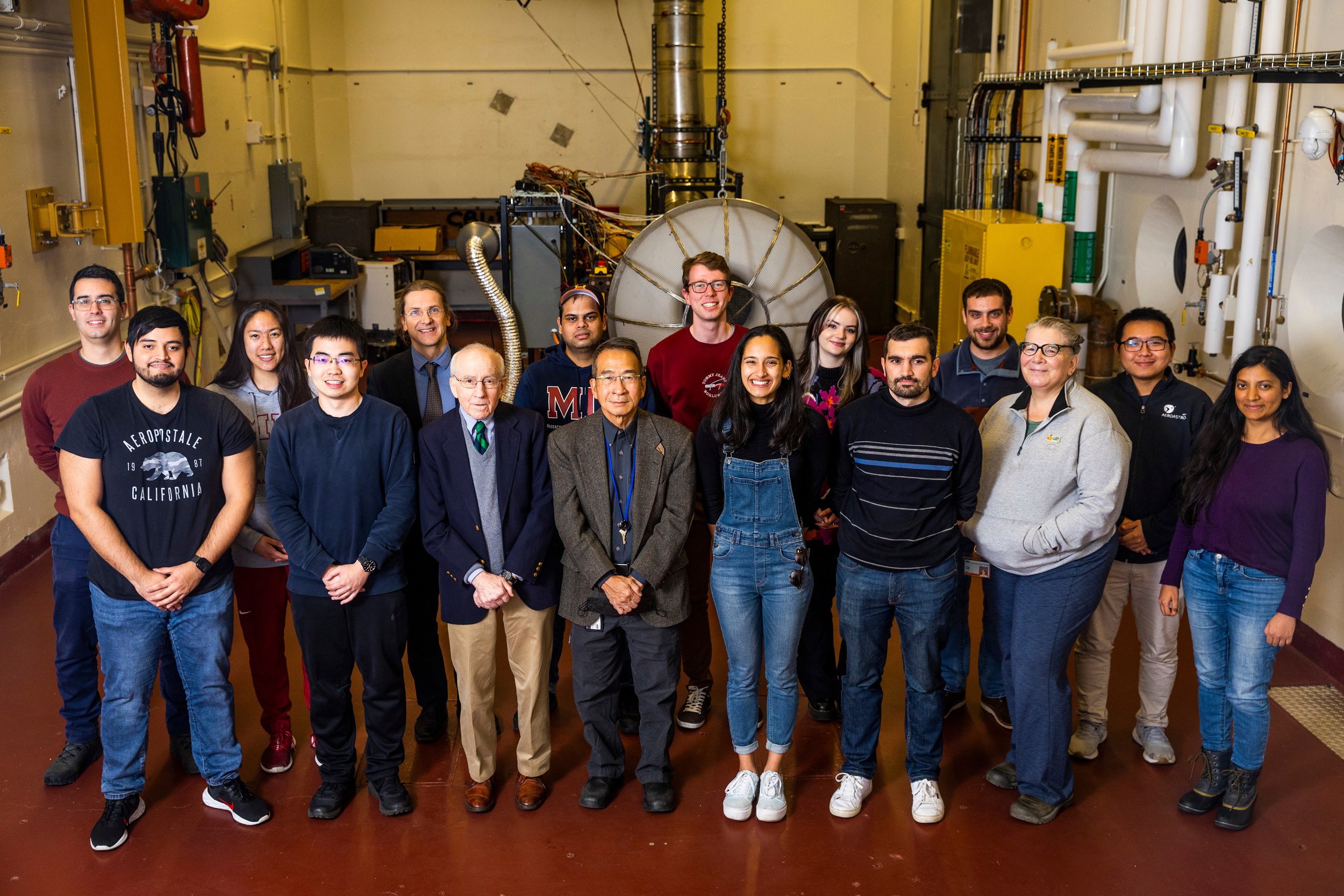
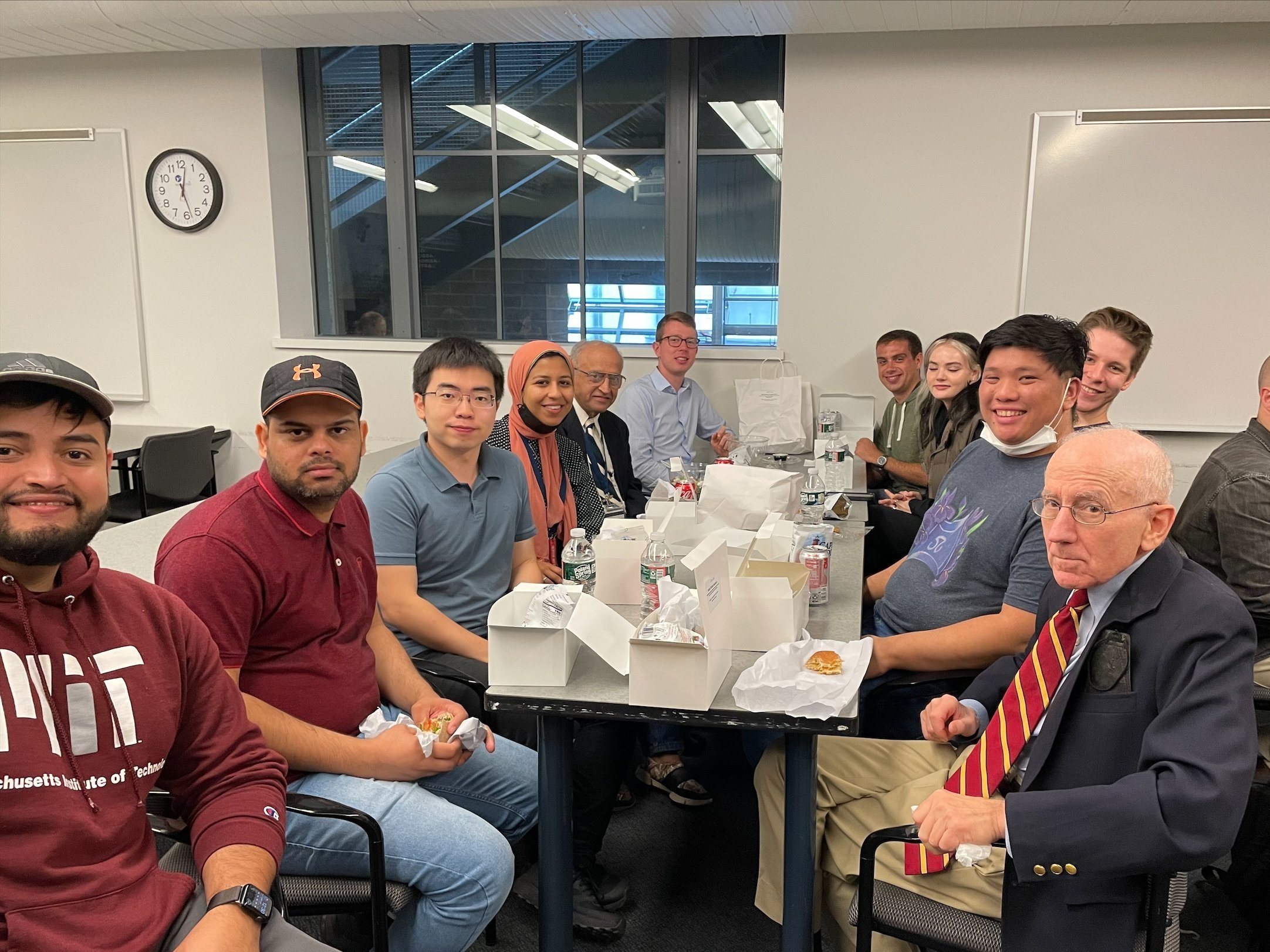
GTL Team