|
Aero-Astro Magazine HighlightThe following article appears in the 2004–2005 issue of Aero-Astro, the annual report/magazine of the MIT Aeronautics and Astronautics Department. © 2005 Massachusetts Institute of Technology. Learn more about/download the Aero-Astro publication. Aspirated compressors = shorter, lighter engines: a boon for supercruising jetsby Jack L. Kerrebrock Gas turbine engines are, in theory, simple . They comprise three main parts: a compressor for squeezing incoming air; a combustion chamber for burning fuel, producing high-pressure and velocity gas; and a turbine that extracts some of the power from the flow to drive the compressor. In the following article, Professor Emeritus Jack Kerrebrock provides a brief non-technical view of the research on aspirated compressors, historical and ongoing, at the MIT Aeronautics and Astronautics Department’s Gas Turbine Laboratory. By aspirated compressors we mean a class of compressors in which the flow is improved by extracting a small fraction of low-energy flow at locations where its accumulation would decrease the pressure rise and increase in losses by deviating the main flow from the intended path. In axial flow compressors these locations typically are on the low-pressure surface of the blades, just ahead of the deceleration of the flow toward the trailing edge, at points of shock impingement, and in corners where the blades join the inner and outer casings of the flow path. A principal advantage of aspirated compressors is that they require fewer stages compared to competitive non-aspirated designs. This enables shorter, hence lighter, engine designs, which are especially attractive for aircraft that cruise supersonically. Supersonic aircraft tend to have high fuel consumption relative to subsonic aircraft, so the fixed weight is very critical. To assist the uninitiated in following the remainder of this discussion, a few points of context may be helpful. First, we are mainly interested in compressors such as are used in the inlet portion of aircraft engines, including the fans and the initial stages of core compressors. The flow is generally axial and transonic, meaning that the speed of the rotating blades, and, hence, the relative flow velocity, is in the range from just below to just above sonic. This is a result of two facts of nature: first, the fractional temperature rise of the flow through the compressor varies as the square of the blade speed, placing a premium on higher blade speeds; second, as the flow becomes supersonic, shock waves can form, causing entropy increases that lower the efficiency of the compression process. Since these losses [losses? I know that an increase in entropy implies a loss in total pressure and reduction in efficiency, but will everyone else?]increase rapidly with Mach numbers exceeding unity, the designs tend to optimize with Mach numbers relative to the blades ranging from a minimum of about 0.8 at smaller radii to a maximum of 1.5 near the tips of the rotating blades. This has led to the characterization of such compressors as “transonic.” A third fact of nature is that in this (transonic) range of Mach number, the mass flow per unit of stream tube area varies slowly with Mach number (peaking at M = 1), so that a small variation in the area of a flow stream tube can result in a relatively large variation in Mach number or velocity. This variation can be smooth and lossless, or it can be abrupt if due to shock waves. It follows that the development of low-speed flow regions on the blade surfaces, even though confined to thin boundary layers, can have strong effects on the flow through the compressor blading. By providing a means to locally modify the flow per unit area, aspiration by removal of boundary layer fluid or other flow that would tend to reduce the available flow area and thereby cause the formation of shocks, or cause the flow to otherwise deviate from the designer’s intent, is a powerful tool for enabling higher pressure rise in both the rotating and the stationary blades of compressors. [break prior sentence into two parts] It is this potential that we seek to exploit in our aspirated compressors.
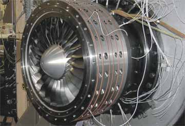
INITIAL DEVELOPMENTThese general ideas have long been understood within the small community of compressor designers. However, it is only recently that design tools have been developed that enable the designer to accurately take account, during the design process, of the effects of subtle variations in the geometry of the compressor flow path, and of the interactions of the stream tubes as they pass through the blading. The first step toward this capability came with the development of Computational Fluid Dynamic techniques capable of dealing with transonic flows, but these were initially analysis techniques, capable of describing the flow through passages of prescribed geometry. They were not very useful for compressor design, the objective of which is to find a geometry that will yield a flow field of a desired character. The desired character includes the rate of pressure rise on the low-pressure (suction) surface of the blade, shock locations and strengths, and other features that control the pressure rise through the blades, and the losses that determine the efficiency of the compressor. The next important step came in the 1980s with the development of the MISES design approach by Aero-Astro Professor Mark Drela and Master’s candidate Harold Youngren. In this approach the flow is divided into a set of interacting stream tubes, two being the boundary layers on the blade surfaces and several describing the inviscid flow between them. It is capable of describing the response to quite subtle variations in blade shape, with modest computing requirements. Equally important to the discussion, it is capable of accurately representing the effect of aspiration on the flow, as mass flow reduction occurs in the stream tube adjacent to the point of aspiration. At about the same time as the development of MISES, this author and his students embarked on experimental efforts to demonstrate the efficacy of aspiration in transonic compressors. The first serious attempt was by doctoral student Duncan Reijnen, who added aspiration scoops to the suction sides of several blades of an existing transonic compressor. This yielded positive effects, but was limited from the outset by the fact that not all blades had aspiration. Clearly, the next step was to develop and test a stage in which it would be possible to fully exploit the advantages of aspiration by designing for a higher pressure ratio than would be possible with aspiration. FULLY ASPIRATED STAGESSupport was obtained from the Air Force Office of Scientific Research to undertake the design and test of a fan stage, with a pressure ratio of about 1.6 at a tip speed of about 750 ft/s. (For non-aspirated stages a speed of about 1300 ft/s would be required to give this pressure ratio.) Dr. Ali Merchant, an Aero-Astro research engineer who had worked with Mark Drela, undertook to modify MISES to meet the needs of the turbomachinery geometry, and to carry out the aerodynamic design. MISES had previously been used mostly for external aerodynamics. Brian Schuler undertook the construction of the stage and its test in the MIT blowdown compressor as his Ph.D. thesis. Shortly after the initiation of this work, we were fortunate to receive support from the Defense Advanced Research Projects Agency for an accelerated and expanded program as part of its MAFC (Micro Adaptive Flow Control) program, under the enlightened management of Dr. Richard Wlezien. This included more money for the low tip speed fan, and substantial funding for a very ambitious high-pressure ratio fan, to be designed and built by MIT and tested at NASA Glenn Research Center. After some preliminary calculations, the design pressure ratio was set at 3.5 at a tip speed of 1,500 ft/s. The speed is typical of first stages in engines, but the pressure ratio would normally be below 2. To add credibility to the work and speed it along, collaboration was sought and received from Pratt &Whitney in the design phase, and from Honeywell Aircraft Engines in the mechanical design. Both of these stages were conceived as critical tests of our capability for designing stages to capture the potential advantages of aspiration. The low tip speed stage should be viewed as a test of the viability of the MISES-based design system, free of mechanical challenges because of the low stress, short time environment of the blowdown compressor. The high-pressure ratio stage was a more severe test of the aerodynamic design and also a test of the viability of aspiration in a high speed stage suitable for use as the first stage in an engine. Both rotors were designed with shrouds at the tips, to minimize the aerodynamic limitations due to tip clearance leakage, and also to provide a simple means for removal of the aspirated flow from the rotor. This flow was transferred outward in the blade, collected in the shroud, and from there transferred to a peripheral collection manifold. The benign environment of the blowdown compressor made it possible to form the suction passages in the rotor of the low tip speed fan by means of cover plates attached mechanically over cavities machined into the aluminum rotor. This was not feasible for the high-pressure ratio rotor and stator, so they were each assembled from front and rear halves, the suction passages being machined into the halves from the parting surface. This construction is shown in Figure 1. Because of the high tip speed, it was necessary to support the shroud of the high-pressure ratio rotor with a graphite/epoxy circumferential winding, also shown in the drawing. In itself, this mechanical arrangement offers some interesting tales, but they will be dispensed with in consideration of their rather arcane appeal. Both of these stages met their design objectives, producing their respective design pressure ratios and mass flows at design speed. They therefore provide two distinct validations of the MIT/NASA design and analysis system for aspirated stages. The high-pressure ratio stage in addition demonstrated the viability of aspiration in a simulated engine environment. It was possible to explore the flow in the low tip speed fan in some detail, and the results are documented in Schuler’s Ph.D .thesis and in a publication. Cost and schedule pressures prevented exploring the flow in the high pressure ratio stage as fully as we would have liked, so we have had to settle for the fact that “it worked.” In any case, it provided a solid basis for further exploration of aspirated compressors.
ONGOING WORK — COUNTER-ROTATIONWith the success of these two aspirated stages, we sought to expand the verified design space to include multiple stages. A possibility that offered new challenges, and was enticing to Aero-Astro Professor Alan Epstein, Merchant, and this author, was a pair of counter-rotating stages. The principal advantage of counter-rotation is that swirl from the first stage augments the work capacity of the second, so that a compressor made up of two counter-rotating rotors, without stators, can be shorter and lighter than a two-stage co-rotating compressor. Such an arrangement can have additional advantages associated with the turbine stages required to drive the two compressor rotors. In the applications envisioned for such an arrangement, tip shrouds are not viable because of the high temperature, so the aspirated flow from the rotors must be exhausted inward, rather than outward as was done in the first two stages. This presented an additional set of challenges to the design system. This proposition was attractive to DARPA, which is funding a program to design, build, and test a counter-rotating two-stage compressor in the blowdown mode at MIT. Dr. John Adamczyk of NASA Glenn has [doesn’t mention him previously so the “again” doesn’t quite fit] participated in the analysis of the design. As of this writing, the apparatus for this experiment is being assembled. Data is expected by the end of 2004. Dr. Gerald Guenette, a principal research engineer in the Gas Turbine Lab, has the lead for the experiment, while Merchant has carried out the design. Epstein is in charge. POSSIBILITIES FOR THE FUTUREAs noted at the beginning, aspirated compressors have fewer stages compared to non-aspirated designs making possible lighter engines designs, which are a plus for supersonic-cruising aircraft. This is because they tend to have high fuel consumption relative to subsonic aircraft, so the weight is very critical. Ali Merchant has now proposed a design that combines a short supersonic diffuser with a supersonic inflow, subsonic outflow fan. This design would make possible a compression system about half the length and weight of a conventional design, in which the flow is diffused to subsonic speed, and then taken into the engine. This arrangement poses a whole new set of challenges to our design system. We look forward to addressing these challenges in coming years. Jack L. Kerrebrock, Professor Emeritus of Aeronautics and Astronautics, served on the MIT faculty from 1960 to 1996. He was head of the Aeronautics and Astronautics Department from 1978 to 1981 and from 1983 to 1985, Associate Dean of Engineering from 1985 to 1989, and Acting Dean from 1989 to 1990. A national Academy of Engineering member and an Honorary Fellow of the American Institute of Aeronautics and Astronautics, Kerrebrock’s research activities have focused on propulsion and power generation. He may be reached at kerbrock@mit.edu |
||||||||
|
|
|
|