The Neural
Control of Visually Guided Eye Movements
D. Temporal Factors in Visually Guided Saccadic Eye Movements
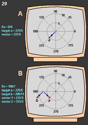
 Figure
29 delineates the conventions we shall use in presenting data
about express saccades in this section. We use a coordinate system in
which each position on the screen is defined by two numbers: the radial
angle in degrees (0° is horiontal left, 90° is up, 180° is
left and 270° is down) and the linar distance from the center of the
screen in degrees of visual angle. Thus 0/0 designates the center of the
screen where the fixation spot (white disk) is located in the upper display
(A). The red target (a) is positioned at 225/5.
The vector of the saccade made to it is 225/5 (direction/amplitude). In
the lower display (B) the white fixation spot is placed at 180/7. Two
targets are shown, a and b.
Target a is in the same position as in the upper
display (225/5). An accurate saccade made to this target now, starting
from the new fixation spot has a vector of 315/5. The second target, b,
is located at 200/11. The saccadic vector to this target b
is 225/5. Thus while the fixation spot and target b in the lower display
are in different positions from those in the upper display, the saccadic
vector to target b is the same as that made
to target a in the upper display. Figure
29 delineates the conventions we shall use in presenting data
about express saccades in this section. We use a coordinate system in
which each position on the screen is defined by two numbers: the radial
angle in degrees (0° is horiontal left, 90° is up, 180° is
left and 270° is down) and the linar distance from the center of the
screen in degrees of visual angle. Thus 0/0 designates the center of the
screen where the fixation spot (white disk) is located in the upper display
(A). The red target (a) is positioned at 225/5.
The vector of the saccade made to it is 225/5 (direction/amplitude). In
the lower display (B) the white fixation spot is placed at 180/7. Two
targets are shown, a and b.
Target a is in the same position as in the upper
display (225/5). An accurate saccade made to this target now, starting
from the new fixation spot has a vector of 315/5. The second target, b,
is located at 200/11. The saccadic vector to this target b
is 225/5. Thus while the fixation spot and target b in the lower display
are in different positions from those in the upper display, the saccadic
vector to target b is the same as that made
to target a in the upper display.
We shall examine the express saccade phenomenon
by posing a series of questions about the conditions under which they
do and do not arise and will then proceed to make inferences about the
brain structures involved. All the data shown were obtained in monkeys.
|