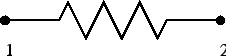
This is a spring element defined between two nodes (Figure 75). The force needed in node 2
to extend the spring with original length ![]() to a final length
to a final length ![]() is given
by:
is given
by:
| (9) |
where k is the spring stiffness and
![]() is a unit vector pointing
from node 1 to node 2. The force in node 1 is
is a unit vector pointing
from node 1 to node 2. The force in node 1 is
![]() . This formula
applies if the spring stiffness is constant. It is defined using the
*SPRING keyword card. Alternatively, a nonlinear spring
can be defined by providing a graph of the force versus the elongation. In
calculations in which NLGEOM is active (nonlinear geometric calculations) the
motion of nodes 1 and 2 induces a change of
. This formula
applies if the spring stiffness is constant. It is defined using the
*SPRING keyword card. Alternatively, a nonlinear spring
can be defined by providing a graph of the force versus the elongation. In
calculations in which NLGEOM is active (nonlinear geometric calculations) the
motion of nodes 1 and 2 induces a change of
![]() .
.
The two-node three-dimensional spring element is considered as a genuine three-dimensional element. Consequently, if it is connected to a 2D element with special restraints on the third direction (plane stress, plane strain or axisymmetric elements) the user has to take care of the third dimension does not induce rigid body motions in the spring nodes. An example of how to restrain the spring is given in test example spring4.