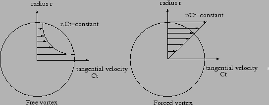
A vortex arises, when a gas flows along a rotating device. If the inertia of the gas is small and the device rotates at a high speed, the device will transfer part of its rotational energy to the gas. This is called a forced vortex. It is characterized by an increasing tangential velocity for increasing values of the radius, Figure 98.
Another case is represented by a gas exhibiting substantial swirl at a given radius and losing this swirl while flowing away from the axis. This is called a free vortex and is characterized by a hyperbolic decrease of the tangential velocity, Figure 98. The initial swirl usually comes from a preceding rotational device.
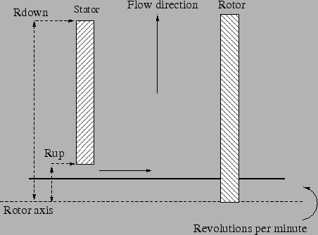
The forced vortex, Figure 99 is geometrically characterized by its
upstream and downstream radius. The direction of the flow can be centripetal
or centrifugal, the element formulation works for both. The core swirl ratio ![]() , which takes values
between 0 and 1, denotes the degree the gas rotates with the rotational
device. If
, which takes values
between 0 and 1, denotes the degree the gas rotates with the rotational
device. If ![]() there is not transfer of rotational energy, if
there is not transfer of rotational energy, if ![]() the
gas rotates with the device. The theoretical pressure ratio across a forced
vertex satisfies
the
gas rotates with the device. The theoretical pressure ratio across a forced
vertex satisfies
![$\displaystyle \left ( \frac{p_o}{p_i} \right ) _{theoretical}= \left[ 1 + \frac...
... ( \frac{R_o}{R_i} \right ) ^2 -1 \right) \right ] ^ {\frac{\kappa}{\kappa-1}},$](img364.png) |
(21) |
where the index ``i'' stands for inside (smallest radius), ``o'' stands for outside (largest radius), p is the total pressure, T the total temperature and U the tangential velocity of the rotating device. It can be derived from the observation that the tangential velocity of the gas varies linear with the radius (Figure 98). Notice that the pressure at the outer radius always exceeds the pressure at the inner radius, no matter in which direction the flow occurs.
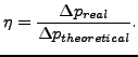
The pressure correction factor ![]() allows for
a correction to the theoretical pressure drop across the vortex and is defined
by
allows for
a correction to the theoretical pressure drop across the vortex and is defined
by
 |
(22) |
Finally, the
parameter ![]() controls the temperature increase due to the vortex. In
principal, the rotational energy transferred to the gas also leads to a
temperature increase. If the user does not want to take that into account
controls the temperature increase due to the vortex. In
principal, the rotational energy transferred to the gas also leads to a
temperature increase. If the user does not want to take that into account
![]() should be selected, else
should be selected, else ![]() or
or ![]() should be
specified, depending on whether the vortex is defined in the absolute
coordinate system or in a relative system fixed to the rotating device,
respectively. A relative coordinate system is active if the vortex element is
at some point in the network preceded by an absolute-to-relative gas element
and followed by a relative-to-absolute gas element. The calculated temperature
increase is only correct for
should be
specified, depending on whether the vortex is defined in the absolute
coordinate system or in a relative system fixed to the rotating device,
respectively. A relative coordinate system is active if the vortex element is
at some point in the network preceded by an absolute-to-relative gas element
and followed by a relative-to-absolute gas element. The calculated temperature
increase is only correct for ![]() . Summarizing, a forced
vortex element is characterized by the following constants (to be specified in
that order on the line beneath the *FLUID SECTION,
TYPE=VORTEX FORCED card):
. Summarizing, a forced
vortex element is characterized by the following constants (to be specified in
that order on the line beneath the *FLUID SECTION,
TYPE=VORTEX FORCED card):
For the free vortex the value of the tangential velocity ![]() of the gas at entrance is the most important
parameter. It can be defined by specifying the number
of the gas at entrance is the most important
parameter. It can be defined by specifying the number ![]() of the preceding
element, usually a preswirl nozzle or another vortex, imparting the tangential
velocity. In that case the value
of the preceding
element, usually a preswirl nozzle or another vortex, imparting the tangential
velocity. In that case the value ![]() is not used. For centrifugal flow the value of the imparted
tangential velocity
is not used. For centrifugal flow the value of the imparted
tangential velocity
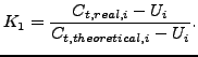
![]() can be further modified by the swirl loss factor
can be further modified by the swirl loss factor ![]() defined by
defined by
 |
(23) |
Alternatively, if the user
specifies ![]() , the tangential velocity at entrance is taken from the
rotational speed
, the tangential velocity at entrance is taken from the
rotational speed ![]() of a device imparting the swirl to the gas. In that case
of a device imparting the swirl to the gas. In that case ![]() and
and ![]() are not
used. The theoretical pressure ratio across a free
vertex satisfies
are not
used. The theoretical pressure ratio across a free
vertex satisfies
![$\displaystyle \left ( \frac{p_o}{p_i} \right ) _{theoretical}= \left[ 1 + \frac...
...eft ( \frac{R_i}{R_o} \right ) ^2 \right) \right ] ^ {\frac{\kappa}{\kappa-1}},$](img381.png) |
(24) |
where the index ``i'' stands for inside (smallest radius), ``o'' stands for outside (largest radius), ``up'' for upstream, p is the total pressure, T the total temperature and Ct the tangential velocity of the gas. It can be derived from the observation that the tangential velocity of the gas varies inversely proportional to the radius (Figure 98). Notice that the pressure at the outer radius always exceeds the pressure at the inner radius, no matter in which direction the flow occurs.
Here too, the pressure can be corrected by a pressure correction factor
![]() and a parameter
and a parameter ![]() is introduced to control the way the
temperature change is taken into account. However, it should be noted that for
a free vortex the temperature does not change in the absolute
system. Summarizing, a free vortex element is characterized by the following constants (to be specified in
that order on the line beneath the *FLUID SECTION,
TYPE=VORTEX FREE card):
is introduced to control the way the
temperature change is taken into account. However, it should be noted that for
a free vortex the temperature does not change in the absolute
system. Summarizing, a free vortex element is characterized by the following constants (to be specified in
that order on the line beneath the *FLUID SECTION,
TYPE=VORTEX FREE card):
Example files: vortex1, vortex2, vortex3.