
March 1998
The impact of the vertical profile of the horizontal wind in the troposphere and lower stratosphere on the development of vertical transport of chemical species induced by deep convective events has been studied using a two-dimensional cloud ensemble model. Seven horizontal wind profiles, including one observed during the Central and Equatorial Pacific Experiment (CEPEX) have been chosen. These represent typical wind profiles over the tropical Pacific including upper level westerly and easterly cases, and have been applied to the model as initial conditions to carry out the sensitivity runs. We have found that the pattern of the shear in the horizontal wind in the vicinity of the tropopause plays a significant role in controlling the development of deep convective clouds. As a result, fluxes of chemical species from the planetary boundary layer to the free troposphere and from the free troposphere to the lower stratosphere are very different for different assumed profiles. It has been found specifically that a moderate wind shear crossing tropopause favors vertically advective transport of chemical species. Strong positive shear, though enhancing turbulent mixing from the troposphere to the stratosphere, generates the weakest vertically advective transport primarily due to its influence in limiting the vertical development of convective turrets. In addition we have found that the smoothed wind profile derived from a more fluctuating observed profile produces clear differences in cloud development and associated tracer vertical transport compared to the results of the run with the non-smoothed profile.
1. Introduction
Vertical transport of trace species emitted into or generated in the planetary boundary layer (PBL) up into the free troposphere and lower stratosphere is of some importance to atmospheric chemistry and global climate change studies. Among all the known mechanisms, deep convective clouds are believe to play the most significant role in this type of transport (e.g., Dickerson et al., 1987; Wang et al., 1995; Cotton et al., 1995; Pickering et al., 1996). Due to the complicated dynamical, physical and chemical processes associated with deep convective clouds, the vertical transport of trace chemicals occurring in them can be influenced by many internal and environmental factors. For instance, the vertical variations in thermodynamic quantities and horizontal wind affect the scale of updrafts and downdrafts, and the growth speeds of convective cells and hence the vertical fluxes of chemical species. Also the large amount of liquid and ice phase particles commonly associated with deep convection can significantly change the transport of chemical species in and around clouds. These particles, while falling toward the ground, scavenge soluble gases on their surfaces or release chemicals to the gas phase through evaporation, both leading to redistribution of chemical species. For the same reason, the relative importances of these factors in affecting the vertical transport of chemical species have yet to be revealed in detail.
Here we report a study of the impact of one of these possible factors, the horizontal wind profile in the troposphere and lower stratosphere, on the vertical transport of trace gases occurring in deep convective clouds. For this study we use a two-dimensional cloud ensemble model and modified wind profiles derived from observations as part of the initial conditions of the model. In the following sections, we briefly describe the model and design of the numerical experiments, and then discuss the implications of the results for trace species transport.
2. Model and Simulations
The model used in this study is a two-dimensional version of a three-dimensional model of cloud dynamics, microphysics, and chemistry (Wang and Chang, 1993). It has a non-hydrostatic, pseudo-elastic dynamic framework and prognostic equations for mixing ratios and number concentrations of cloud droplets, rain drops, ice crystals, and graupel. A version of this model with transport only chemistry (Wang et al., 1995) has been used in this study due to the assumed chemical inertness of the simulated species, dimethylsulfide (DMS) on the time scales of the convective events. The resolution of the model is 2 km horizontally and 0.5 km vertically. The model dimensions are 1000 km in the horizontal and 25 km in the vertical direction. An open lateral boundary condition has been used.
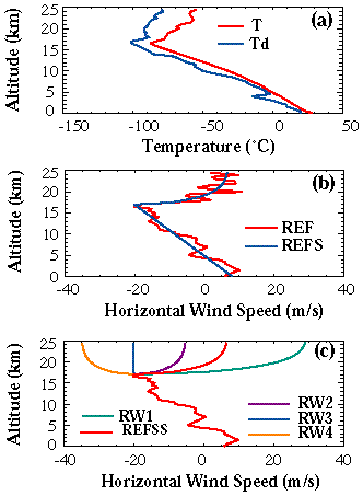
The initial profiles for temperature and dew point temperature (Figure 1a) are taken from the sounding launched during the Central and Equatorial Pacific Experiment (CEPEX, Ramanathan et al., 1993) for the March 8, 1993 deep convective event. Dimethylsulfide was assumed to initially exist only below a 2 km altitude with a constant mole fraction of 50 ppt. We conducted two sets of simulations in this study using the same initial profiles for temperature, dewpoint temperature, and DMS mole fraction but different initial profiles for horizontal wind. The first set contains two simulations: the reference run REF using the observational profile and the REFS run using a smoothed profile derived from the observational one as their initial profiles for horizontal winds (Figure 1b). This first set is designed to gauge the influence of the fluctuations in wind shear on the cloud development and associated tracer transport. To explore the impact of different wind profiles in the lower stratosphere on the vertical transport of DMS, five simulations have been carried out in the second set. In these runs we use five different initial profiles for horizontal winds (Figure 1c) with the same tropospheric part as in the above observational profile but different assumed stratospheric parts ranging from easterly to westerly winds (RW1, REFSS, RW2, RW3, and RW4).

Figure 1. Initial profiles of (a) temperature and dew point temperature, and horizontal wind speed used in (b) Simulation Set 1 and (c) Simulation Set 2.
The integrations in each case lasted 16 hours. The simulated deep convective tower formed at about 750 km from the left boundary of the model domain where the initial disturbance, a 14 by 3 km "warm bulb" with temperature up to 1.5 degree warmer than that of environment, was applied. The associated cloud started to dissipate after about 5 hours of integration but still exhibited on an expanded anvil after (Figure 2). The impact of the different wind profiles on the cloud development is quite significant. For example, as shown in Figure 2, the smoothed profile used in the run REFS leads to more intense precipitation, and a wider tower region, compared to the run REF. Figure 3 shows the mean vertical velocities and mixing ratios of total condensed water in the convective regions of the clouds as functions of time in all seven runs. We find that the cloud time evolution is quite different in the run REFS which uses the smoothed initial wind profile in the troposphere than in the other six runs (that all use the non-smoothed observed initial wind profile in the troposphere). The peak convection is stronger and the cloud development is about half an hour earlier in REFS than in the other runs. The reason for this difference is that the smoothed wind profile has significantly changed the wind shear pattern from its original status. From Figure 1b we see that the horizontal wind speed differs by up to 5 m/s at several levels in the troposphere between the REF and REFS profiles. Without the reversed shear layers in the troposphere, convective cells develop more rapidly in the initial stage. The influence of the wind profile in the lower stratosphere on the cloud development is also evident. We find from Figure 3 that the simulated clouds dissipate earlier in the only run with negative shear in the wind across the tropopause (RW4) and in another run with the largest positive wind shear across the tropopause (RW1) among runs in the second simulation set.
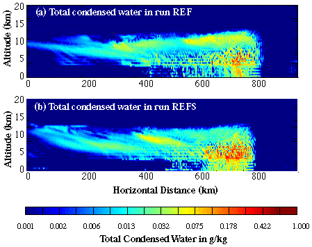
Figure 2. Distribution of mixing ratio of total condensed water (summation of cloud water, rain, ice crystals, and graupel) in g/kg after 10 hours of model integration time in (a) run REF and (b) run REFS.
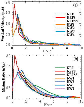
Figure 3. Time evolution of mean values of (a) vertical velocities and (b) mixing ratios of total condensed water in convective regions in all seven runs. The convective regions in these runs are the cloud regions horizontally ranged from 600 to 900 km from left boundary of the model domain.
During the simulations, DMS was brought into the free troposphere through the convective tower, and then appeared to be transported along with the expanding cloud anvil. After 8 hours of integration, DMS had been transported horizontally as far as 600 km from the convective tower (Figure 4). In the far end of the anvil, clear evidence of vertical transport of DMS into the lower stratosphere is found, except for the RW4 run. The spreading patterns of DMS in the lower stratosphere clearly depend on the wind shear pattern across the tropopause. In those cases illustrated with positive shears across the tropopause (runs REF, REFS, and RW1 in Figure 4a-4c), the strong turbulent mixing and reversed horizontal wind direction across the tropopause form a DMS trail in the lower stratosphere spreading from west to east. In contrast, the negative shear case (RW4 in Figure 4d) has weak transport of tracers across the tropopause to the lower stratosphere. Note by comparing Figure 4a and 4b we can see the DMS distributions in troposphere are also influenced by the tropospheric horizontal wind profiles.

Figure 4. Distributions of dimethylsulfide (mole fractions in parts per trillion, or ppt) after 8 hours of model integration time in runs (a) REF, (b) REFS, (c) RW1 and (d) RW4.
Figure 5 shows domain-averaged vertical profile of DMS at 10 hours in integration. Above the lowest 2 km of the troposphere, where DMS is assumed to resident initially, domain-average mole fraction of DMS reaches its lowest value between about 6-9 km in height then increases in the layer between 10-15 km corresponding to the vertical location of the stratiform part of the cloud. This result suggests that the DMS transport is primarily vertical below 9 km then switches to the horizontal direction above. It is this horizontaly oriented transport above 9 km that sends DMS to a much wider spatial range. As a result, the domain average mole fractions of DMS above a 9 km level are clearly higher than their values in the middle part of the troposphere (6-9 km) in all seven runs. The differences among different runs are quite evident above the 5 km height in Figure 5. The RW4 run produces the lowest mole fraction of DMS in the layer between 6-9 km height, which is nearly 40% lower than that in the REFS run. Above tropopause (~17 km), DMS concentrations produced by RW3 and RW4 are one order of magnitude lower than those produced by the other runs.
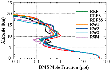
Figure 5. Domain-average mole fractions of DMS in ppt at 10 hours of integration time and as functions of altitude in all seven runs.
3. Analysis of Simulations
To investigate the integrated features of tracer transport as impacted by different horizontal wind profiles, we define a parameter called the "domain accumulated DMS amount" (D), We derive D by integration over time t of the DMS flux F(t, x, L) through a horizontal surface at altitude L due to vertical advection (W-Flux) and turbulent diffusion (K-Flux) during the simulation:

where L = 2 km or 17 km (tropopause), and MX represents the size of the model domain in the horizontal (x) direction (1000 km). As a result of wind shear, the fluxes of DMS from the planetary boundary layer (PBL) through L = 2 km to the free troposphere, and from the troposphere through L = 17 km to the lower stratosphere, are very different for the seven chosen wind profiles. We find in Simulation set 1 that using a smoothed horizontal wind profile (i.e., the run REFS), instead of the observed one with its significant fluctuations, produces different D values across both L = 2 km and L = 17 km compared to the results from the run REF which uses the observed profile. Particularly in our case, although the D values for the K-Flux across L = 17 km in both the REF (2.1 x 10⁻⁵ kg) and REFS (2.3 x 10⁻⁵ kg) runs are quite close, the D value for the W-Flux across the same vertical surface from the run REFS is more than double the value from the run REF (2.1 x 10⁻⁵ vs. 9.3 x 10⁻⁶ kg). The similar phenomenon is also found in D fluxes across L = 2 km. Earlier and stronger development of convection in the REFS run compared to that in the REF run (Figure 3) obviously contributes to this difference.
In the Simulation Set 2, transport differences attributed to the various wind profiles are even more significant than in the first simulation set. Figure 6a shows that the transport of DMS through L = 2 km by vertical advection minimizes for the two moderate wind shear cases (REFSS and RW4) but maximizes for another moderate wind shear case (RW2), the no shear run (RW3), and the run with largest positive shear (RW1). The interesting fact is that the vertical advective transport appears to not follow exactly the stratospheric wind shear differences among these runs. From detailed analyses we find that the convective region and surrounding area (about 400 km around the convective core) are the places where the primary differences in vertical transport of DMS across L = 2 km exist. We furthermore find that both position and strength of precipitation seem responsible for this difference. In the RW3, RW1, and RW2 runs, average mixing ratios of rainwater in the lowest 2 km of the atmosphere inside the convective region appear to be larger than those are in the REFSS and RW4 runs. Heavier precipitation in this convective region generates stronger divergence and vertical perturbations that eventually cause higher vertical fluxes of tracer around 2 km height, especially in the downwind side in the lower atmosphere (toward right boundary of the model domain in our case). This is definitely an interesting issue for future investigation using three-dimensional model. The vertical transport by turbulent mixing (Figure 6b) appears to be similar in both amount and evolution in all five runs so the differences at L = 2 km are determined largely by advection.
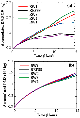
Figure 6. Domain-accumulated DMS across 2 km due to (a) W-Flux, and (b) K-Flux.
Figure 7a shows the integrated vertical advective fluxes through L = 17 km. The three runs using the moderate wind shear profiles (RW2 followed by RW4 and REFSS) provided significantly higher contributions to D than the other two runs. Apparently, the strong westerly wind shear in the RW1 run enhances downward fluxes in both the tower and anvil regions which leads to weaker vertical transport across the tropopause. Compared to the monotonic behavior for integrated vertical advection through L = 2 km to the free troposphere (Figure 6a), evolution of net advective transport of DMS across the tropopause appears to be more complicated. A strong downdraft around the cloud top level after 4 hours generated a negative trend in the advective contribution to D in all five cases. After about 7-8 hours, the domain accumulated amount of DMS across the tropopause started increasing again due to updrafts occurring outside the convective tower as discussed in the following section. The integrated vertical diffusive fluxes (K-flux) through L = 17 km (Figure 7b) maximize for the largest positive shear run (RW1) apparently due to the higher kinetic instability in these runs.
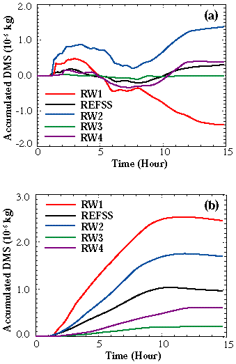
Figure 7. Domain-accumulated DMS across 17 km due to (a) W-Flux, and (b) K-Flux.
The horizontal distribution of vertical transport of DMS due to vertical winds and turbulent mixing, is illustrated using the following alternative version of the domain accumulated DMS amount:

where T represents the total integration time length (16 hours). The horizontal distribution of D* at L = 2 km in the REFSS run (Figure 8a) shows that the vertical advective (W-flux) transport of DMS primarily occurs around the location of the convective tower. Compared with the W-Flux results, transport induced by turbulent mixing (K-flux), which is multiplied by 10 for the Figure 8a and 8b plots, is about one order of magnitude less and occurs quite uniformly along the frontal parttail of the stratiform region of the cloud (toward the left boundary of the model domain).
The convective tower region provided the largest (upward or downward) D* values at 17 km (Figure 8b). However, significant transport by vertical winds also appeared all along the anvil up to some 750 km from the convective tower. Similar to the pattern shown in Figure 8a, the contribution to D* by the K-Flux is close to that due to the W-Flux and follows quite closely the distribution of D* by the W-Flux in shape along the cloud anvil.
To provide further details, we present in Figure 9 the horizontal distributions of the instantaneous fluxes F(t, x, L) induced by the vertical winds (W-Flux) and turbulent mixing (K-Flux) for L = 17 km at three specific times (2 hours, 5 hours, and 10 hours) for the REFSS run. These three times represent different developmental stages of the cloud and correspond to three times when upward advective transport is significant (Figure 7a).
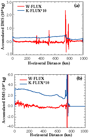
Figure 8. Distribution of accumulated DMS due to fluxes across (a) 2 km and (b) 17 km in run REFSS. Values of K-Flux have been multiplied by a factor of 10.
For the W-Flux contribution to F(t, x, L) (Figure 9a), although the strongest updrafts during the cloud lifetime exist in the same time period, downdrafts in the tower region during the initial developmental stage of the cloud (2 hours) generate significant downward transport of DMS. This is the reason that in our simulation DMS has not been very effectively transported by advection through the top of the convective tower in this early phase. We can still find downward transport with a similar magnitude to the upward transport at 5 hours. At 10 hours, net upward transport occurs as far as 600 km to the left of the tower region.
Figure 9b shows that in the initial developmental stage of the convective cloud (2 hours) the contribution to F(t, x, L) by the K-Flux is not as large as at the two subsequent times due to downward transport and a narrow impacted region which exists only around the convective tower region. Turbulent mixing also generates upward transport of DMS in the later time steps (5 hours and 10 hours) but progressively further away from the tower location and associated with processes at the front edge of the anvil (Figure 4). Analysis of the horizontal distributions of the eddy-transfer coefficient K at 5 and 10 hours shows similar values at different time steps (Figure 10). Hence, we conclude that the location of the peaks at 5 and 10 hours in the K-Flux in Figure 9b are caused largely by the higher mixing ratios of DMS in those places.
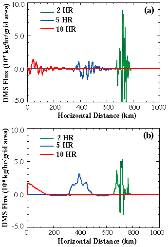
Figure 9. Horizontal distributions of (a) W-Flux and (b) K-Flux of DMS across 17 km at 2, 5, and 10 hours of model integration time in run REFSS.
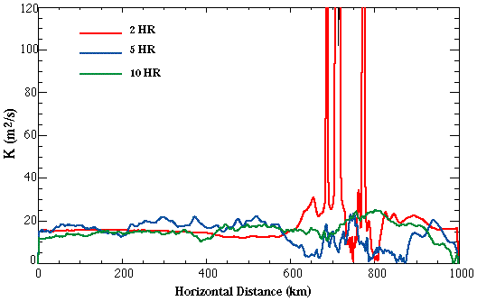
Figure 10. Horizontal distributions of the eddy-transfer coefficient K (m2/s) at 17 km and at 2, 5, and 10 hours of model integration time in run REFSS.
These results show that upward transport of DMS across the tropopause induced both by the vertical winds (W-Flux) and by the turbulent mixing (K-Flux) can occur all along the cloud anvil as well as in the convective cloud tower region, and can occur even as the cloud starts to dissipate. The convective tower produces significant fluxes of DMS both upward and downward. Compared with the largely upward transport patterns in the cloud anvil region, the strong two-way motion generated in the tower region leads to an ineffective net transport there of DMS across the tropopause due to the W-Flux. In addition, our results show no evidence of significant vertical transport of DMS in the upwind side of the convective tower.
4. Conclusions
This research suggests that a careful treatment of horizontal wind profiles is required in numerical simulations of convective transport of trace chemicals when using two-dimensional (and perhaps therefore three-dimensional) models. It also indicates that in the development of parameterization schemes for convective cloud transport in large-scale models, the parameterization should include effects of transport in the remote anvil region as well as the central convective tower region. This research serves as a first step toward using a three-dimensional cloud ensemble model to study the details of deep convective clouds in the vertical transport trace gases from the planetary boundary layer to the free troposphere and lower stratosphere.
Acknowledgments
This research was supported by the MIT Joint Program on the Science and Policy of Global Change, the NASA Grant NAG1-1805, and the NOAA Climate and Global Change Program Grant No. GC97-474. Observational data from the CEPEX experiment were kindly provided by the Center for Clouds, Chemistry, and Climate (C4), at the Scripps Institution of Oceanography. We thank two anonymous reviewers for many helpful comments and suggestions that have helped to improve the manuscript.
References
Cotton, W.R., G.D. Alexander, R. Hertenstein, R.L. Walko, R.L. McAnelly and M. Nicholls, Cloud venting--A review and some new global annual estimates, Earth Science Review, 39, 169-206, 1995.
Dickerson, R.R., G.J. Huffman, W.T. Luke, L.J. Nunnermacker, K.E. Pickering, A.C.D. Leslie, C.G. Lindsey, W.G.N. Slinn, T.J. Kelly, P.H. Daum, A.C. Delany, J.P. Greenberg, P.R. Zimmerman, J.F. Boatman, J.D. Ray and D.H. Stedman, Thunderstorms: An important mechanism in the transport of air pollutants. Science, 235, 460-465, 1987.
Pickering, K.E., A.M. Thompson, Y. Wang, W.-K. Tao, D.P. McNamara, V.W.J.H. Kirchhoff, B.G. Heikes, G.W. Sachse, J. Bradshaw, G.L. Gregory and D.R. Blake, Convective transport of biomass burning emissions over Brazil during TRACE A, J. Geophys. Res., 101(D19), 23,993-24,012, 1996.
Ramanathan, V., R. Dirks, R. Grossman, A. Heymsfield, J. Kuettner and F.P.J. Valero, Central Equatorial Pacific Experiment Design, Center for Clouds, Chemistry, and Climate Report, University of California, San Diego, 115 p., 1993.
Wang, C. and J.S. Chang, A three-dimensional numerical model of cloud dynamics, microphysics, and chemistry. 1. Concepts and formulation, J. Geophys. Res., 98(D8), 14,827-14,844, 1993.
Wang, C., P.J. Crutzen, V. Ramanathan and S.F. Williams, The role of a deep convective storm over the tropical Pacific Ocean in the redistribution of atmospheric chemical species, J. Geophys. Res., 100(D6), 11,509-11,516, 1995.
| Top of page |
| |