 |
 |
WINNER OF THE 1999 BEST REPORT REWARD!!!
| AIR FOIL | ||
| QUESTIONS OR COMMENTS | ||
 |
AUTHOR: | Mealani Nakamura |
| E-MAIL: | mealani@mit.edu | |
| COURSE: | 2 | |
| CLASS/YEAR: | 3 | |
MAIN FUNCTIONAL REQUIREMENT: Provide enough lift to counter the weight of the plane.
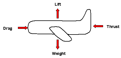
Lift and weight are two of the four forces acting on an airplane, the other two are drag and thrust (see Figure 1).
 |
| Figure 1: The Four Forces Acting on an Airplane |
DESIGN PARAMETER:
Wing (Airfoil)GEOMETRY/STRUCTURE:
The airplane generates lift using its wings. The cross-sectional shape of the wing is called an airfoil. A typical airfoil and its properties are shown in Figure 2, and are also described below.
 |
| Figure 2: Typical Airfoli (Cross-Sectional Shape) of An Airplane Wing |
| Chord: | Extends from leading edge to trailing edge of the wing |
| Camber line: | Points halfway between chord and upper wing surface |
| Angle of attack: | Angle between direction of airflow and the chord |
EXPLANATION OF HOW IT WORKS/ IS USED:
The wings provide lift by creating a situation where the pressure above the wing is lower than the pressure below the wing. Since the pressure below the wing is higher than the pressure above the wing, there is a net force upwards.
To create this pressure difference, the surface of the wing must satisfy one or both of the following conditions. The wing surface must be:
- Cambered (curved); and/or
- Inclined relative to the airflow direction.
Several airfoils are shown in Figure 3. However, the airfoils shown in Figure 3 are useless without viscosity.
 |
| Figure 3: A Few Different
Airfoils Note: There Are An Infinite Number of Possibilities; i.e. a) Flat Bottom; b) Slightly Curved Bottom; c) Symmetrical |
Viscosity is essential in generating lift. The effects of viscosity lead to the formation of the starting vortex (see Figure 4), which, in turn is responsible for producing the proper conditions for lift.
 |
| Figure 4: Starting Vortex Formation |
As shown in Figure 4, the starting vortex rotates in a counter-clockwise direction. To satisfy the conservation of angular momentum, there must be an equivalent motion to oppose the vortex movement. This takes the form of circulation around the wing, as shown in Figure 5. The velocity vectors from this counter circulation add to the free flow velocity vectors, thus resulting in a higher velocity above the wing and a lower velocity below the wing (see Figure 6).
 |
| Figure 5: Circulation of Air Around Wing |
 |
| Figure 6: Vector Addition Results in a Lower Velocity Below The Wing and a Higher Velocity Above The Wing |
The following presents two of several ways to show that there is a lower pressure above the wing than below.
One method is with the Bernoulli Equation, which shows that because the velocity of the fluid below the wing is lower than the velocity of the fluid above the wing, the pressure below the wing is higher than the pressure above the wing.
A second approach uses Euler's Equations (which the Bernoulli equation is derived from) across the streamlines. Due to the curvature of the wing, the higher velocities and acceleration over the top of the wing requires a pressure above the wing lower than the ambient pressure.
Thus, using either of the two methods, it is shown that the pressure below the wing is higher than the pressure above the wing. This pressure difference results in an upward lifting force on the wing, allowing the airplane to fly in the air.
DOMINANT PHYSICS:
Outside of the boundary layer around the wing, where the effects of viscosity is assumed to be negligible, some believe that the Bernoulli equation may be applied. (Note: there is currently much debate over the validity of applying Bernoulli to the flow around an airplane wing. Even here at MIT, there are advocates both strongly for and against the use of this equation.) Simple and neat, the application of the Bernoulli equation, however, requires the flow to be:
- Steady
- Incompressible, and
- Frictionless;
Furthermore, there can be no energy sources or sinks along the streamline. The Bernoulli equation is applied along a streamline, taking the form:
| (P1/p) + (1/2)v12 + gz1 = (P2/p) + (1/2)v22 + gz2 = a constant | (1) |
Where:
Units |
|||
| Variable | Description | Metric | English |
| P | Is the pressure of the fluid, | Pa | psi |
| p | Is the density of the fluid, | kg/m3 | lbm/ft3 |
| v | Is the velocity of the fluid relative to the airfoil, | m/s | ft/s |
| g | Is magnitude of the acceleration for body forces, and | m/s2 | ft/s2 |
| z | Is the height at that point. | m | ft |
The subscripts 1 and 2 indicate different points along the same streamline of fluid flow.
 |
| Figure 7: Points Along a streamline For the Application of the Bernoulli Equation |
Take point 1 to be at a point on the streamline far in front of the wing (see Figure 7). Here, the pressure is P1 = Pambient. Take point 2 to be at a point above the curved surface of the wing, outside of the boundary layer. It is assumed that compared to the other terms of the equation, gz1 and gz2 are negligible (i.e. the effects due to gravity are small compared to the effects due to kinematics and pressure). Thus, Equation 1 becomes:
| (Pambient/p) + (1/2)vambient2 = (Pabove/p) + (1/2)vabove2 = a constant | (2) |
For the second case, take point 1 to be again at a point on the streamline in front of the wing. Since the values for Pambient and vambient are the same as for the first case, the constant from Equation 2 is also assumed to be the same. Take point 2 to be at a point below the wing, outside of the boundary layer. With the same assumptions as in the first case, Equation 1 and 2 become:
| (Pbelow/p) + (1/2)vbelow2 = (Pabove/p) + (1/2)vabove2 = a constant | (3) |
Since the velocity of the fluid below the wing is slower than the velocity of the fluid above the wing, to satisfy Equation 3, the pressure below the wing must be higher than the pressure above the wing.
In a qualitative look at Euler's Equations, the movement of the fluid flow around the curved upper surface of the wing may be likened to that of a car going around a bend.3 As you will learn or have already learned in freshman physics, when the car turns, a force must accelerate the car towards the center of the turn (see Figure 8). Similarly, as the fluid particle follows the cambered upper surface of the wing, there must be a force acting on that little particle to allow the particle to make that turn.
 |
| Figure 8: Centripetal Force on a Car Accelerating Around a Curve |
This force comes from a pressure gradient above the wing surface. Starting at the surface of the wing and moving up and away from the surface, the pressure increases with increasing distance until the pressure reaches the ambient pressure. Thus, a pressure gradient is created, where the higher pressures further along from the radius of curvature push inwards towards the center of curvature where the pressure is lower, thus providing the accelerating force on the fluid particle.
Thus due to the curved, cambered surface of the wing, there exists a pressure gradient above the wing, where the pressure is lower right above the surface. Assuming a flat bottom, the pressure below the wing will be close to the ambient pressure, and will thus push upwards, creating the lift needed by the airplane.
LIMITING PHYSICS:
Stalling:
At angles of attack below around ten to fifteen degrees, the lift increases with an increasing angle. However, if the angle of attack is too large, stalling takes place. Stalling occurs when the lift decreases, sometimes very suddenly. The phenomena responsible for stalling is flow separation (see Figure 9). Flow separation is the situation where the fluid flow no longer follows the contour of the wing surface.
 |
| Figure 9: Flow Separation Due To a Large Angle of Attack |
Fluid particles flowing along the top of the wing surface experience a change in pressure, moving from the ambient pressure in front of the wing, to a lower pressure over the surface of the wing, then back up to the ambient pressure behind the wing. The region where fluid must flow from low to high pressure (adverse pressure gradient) is responsible for flow separation. If the pressure gradient is too high, the pressure forces overcome the fluid's inertial forces, and the flow departs from the wing contour. Since the pressure gradient increases with an increasing angle of attack, the angle of attack should not exceed the maximum value to keep the flow following the contour. If this angle is exceeded, however, the force keeping the plane in the air will decrease, and may even disappear altogether.
PLOTS/GRAPHS/TABLES:
None Submitted
OTHER PLACES YOU CAN FIND AIRFOILS:
GLOSSARY:
Viscosity can be described as the "thickness," or, for a moving fluid, the internal friction of the fluid. Viscosity measures the ability of the fluid to dissipate energy. A parameter of viscosity is the coefficient of viscosity, which is equal to the shear stress on a fluid layer over the speed gradient within the layer.
Viscosity is essential in generating lift; it is responsible for the formation of the starting vortex, which in turn is responsible for producing the proper conditions for lift.
Viscosity is responsible for the formation of the region of flow called the boundary layer. There are two types of boundary layers:
- Laminar
- Turbulent
In a laminar boundary layer, the fluid molecules closest to the surface will slow down a great deal, and appear to have zero velocity because of the fluid viscosity. In turn, these surface molecules create a drag on the particles flowing above them and slow these particles down. The effect of the surface on the movement of the fluid molecules eventually dissipates with distance from the surface. The area where these viscous effects are significant is called the boundary layer.
In a turbulent boundary layer, eddies, which are larger than the molecules, form. The slower eddies close to the surface mix with the faster moving masses of air above. As a result, the air molecules next to the wing surface in a turbulent boundary layer move faster than in a laminar boundary layer (for the same flow characteristics).
A turbulent boundary layer has the following properties over a laminar boundary layer:
- The drag is higher, and
- The turbulent boundary layer is not as susceptible to flow separation.
The two types of boundary layers may thus be manipulated to favor these properties.
A streamline is the path that a fluid molecule follows. Every point along the streamline is parallel to the fluid velocity.
REFERENCES/MORE INFORMATION:
See also on this site: Hydrofoil, Sailboat
- Barnard, R.H. and Philpott, D.R., Aircraft Flight: a description of the physical principles of aircraft flight, Essex, England: Longman Group Limited, 1995.
- Bertin, John J. and Smith, Michael L., Aerodynamics for Engineers, Third Edition, Upper Saddle River, NJ: Prentice-Hall, Inc., 1998.
- Brisson, John, Assistant Professor, Mechanical Engineering Department, January 12, 1999 12:00 PM.
- Hubin, W.N., The Science of Flight: Pilot-oriented Aerodynamics, Iowa: Iowa State University Press/AMES, 1992.
- Perdichizzi, Richard F., Technical Instructor, Aeronautics and Astronautics Department, January 13, 1999 10:00 AM.
- White, Frank M., Fluid Mechanics, New York: McGraw-Hill, Inc., 1994.