 |
 |
| HYDROFOILS | ||
| QUESTIONS OR COMMENTS | ||
|
AUTHOR: | Tina Rosado |
| E-MAIL: | tlrosado@mit.edu | |
| COURSE: | 2 | |
| CLASS/YEAR: | 2 | |
MAIN FUNCTIONAL REQUIREMENT: Lift the boat’s hull outside the water.
DESIGN PARAMETER: Hydrofoil (It is a foil or wing under water used to lift the boat’s hull until it is totally outside the water.)
GEOMETRY/STRUCTURE:
 |
| Detail of Hydrofoil Geometry |
EXPLANATION OF HOW IT WORKS/ IS USED:
1. At low speeds the hull (body of ship) sits in the water and the hydrofoils are totally submerged in the water.
2. As the boat’s speed increases, the hydrofoils create lift.
3. At a certain speed, the lift produced by the hydrofoils equals the sum of of the boat and cargo weights. Therefore the hull comes out of the water.
4. Instead of having an increase in drag with increasing speed because the hull is lifted out of the water (contrary to what happens in traditional boats due to pressure drag), the hydrofoils provide a more efficient way of cruising. Decreasing the drag contributes to the better use of the power needed for the movement of the boat.
DOMINANT PHYSICS:
How is the lift produced - Fluid Dynamics.
For the purpose of this project two explanations will be presented in a general and basic way. These theories are the application of Bernoulli’s Equation and Euler’s Equation for Streamline Curvature Effect.
Bernoulli’s Equation: Po = P1 + ½
rv1² + rgy1 = P2 + ½rv2² + rgy2| Variables | Units |
| Po Stagnation Pressure | [Pa] or [lbf/ft2] |
| P Pressure | [Pa] or [lbf/ft2] |
| r Density | [kg/m3] or [lbf/ft3] |
| V Velocity | [m/s] or [ft/s] |
| g Gravitational Constant | [m/s2] or [ft/s2] |
| y Height | [m] or [ft] |
 |
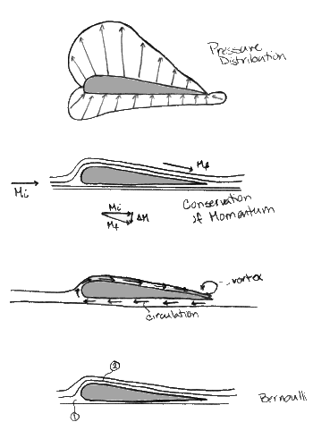
| Detail of Hydrofoil: a) Pressure Profile b) Momentum Transfer c) Circulation d) Streamlines |
As the speed along these streamlines increases,the pressure drops (this will become important shortly). The fluid that moves over the upper surface of the foil moves faster than the fluid on the bottom. This is due in part to visous effects which lead to formation of vertices at the end of the foil. In order to conserve angular momentum caused by the counter-clockwise rotation of the vortices, there has to be an equal but opposite momentum exchange to the vortex at the trailing edge of the foil. This leads to circulation of the fluid around the foil. The vector summation of the velocities results on a higher speed on the top surface and a lower speed on the bottom surface. Applying this to Bernoulli’s it is observed that, as the foil cuts through fluid, the change in velocity produces the pressure drop needed for the lift. As it is presented in the diagram, the resulting or net force (force= (pressure)(area)) is upward. This explanation can be enriched with the Principle of Conservation of Momentum. (Momentum = (mass)(velocity)) If the velocity of a particle with an initial momentum is increased, then there is a reactant momentum equal in magnitude and opposite in direction to the difference of the momentums. (See diagram).(Mi = Mf + DM)
Euler’s Equation: d(p+rgy)/dn = rv²/R
| Variables | Units |
| P Pressure | [Pa] or [lbf/ft2] |
| r Density | [kg/m3] or [lbf/ft3] |
| V Velocity | [m/s] or [ft/s] |
| g Gravitational Constant | [m/s2] or [ft/s2] |
| y Height | [m] or [ft] |
| n Vector in Radial Direction | --- |
| R Radius of Curvature of Streamline | [m] or [ft] |
 |
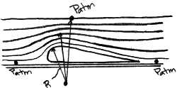
| Detail of Pressure At Points Over An Airfoil |
Here again, the term referring to the height is assumed negligible compared to the other terms in the equation. This equation says that as you go further from the center of the radius of curvature of a streamline, the pressure on the streamlines increases. The upper surface of the foil is closer to the center of curvature of the streamlines, therefore there will be a lower pressure than the ambient pressure above the foil. The difference between the pressure on the top surface and the ambient pressure at the bottom surface will produce a net pressure that will cause the lift.(See diagram.)
Angle of Attack:
 |
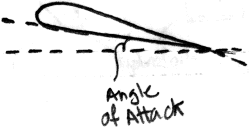
| Angle of Attack |
As it has been presented, lift comes from the dynamics of the fluid in the area surrounding the foil. But the lift can be optimized by positioning the hydrofoil at an angle (relative to the incoming fluid flow) called the angle of attack (See diagram). The goal is to optimize the lift to drag ratio. This ratio depends on the shape of the foil, which in this case is considered to be a thin foil. With a small angle of attack, the lift increases rapidly while the drag increases at a small rate. After an angle of ~10° the lift increases slowly until ~15° where it reaches a maximum. After ~15° stall can set in. When the angle of attack is 3° to 4° the ratio of lift:drag is at it’s maximum. So the foil is more efficient at those angles (3°and 4°) with lift to drag ratios of ~ 20 to 25:1
LIMITING PHYSICS:
 |
| Detail of Hydrofoil Geometry |
At first, people can think that stalling is likely to be a problem in hydrofoils as it is in airfoils, but surprisingly it is not. A steep angle of attack is not needed in the design of the hydrofoil. On the contrary, small angles of attack are used on hydrofoils to optimize the lift to drag ratio as explained before.
What is a primary concern is the design of the foil, the struts/supports, and their positioning. All these features have to be taken in consideration. So the features are designed to produce a minimum speed that will lift the boat of certain weight and keep it foilborne.
One problem that a hydrofoil craft can experience is the height of the waves being greater than the struts. Also, if the craft is traveling faster than the waves, the foils could break to the surface and outside of the water, resulting in a loss of lift and a negative angle of attack when the foil dives into the next wave, making the craft crash into the sea. Engineers have designed hydrofoils to minimize these limitations and better the ship’s performance.
PLOTS/GRAPHS/TABLES:
None Submitted
SOME HYDROFOILS AND THEIR USE:
Hydrofoils have become very popular. They are used in various kind of sea traveling, from military use to watersports. The high speed, smooth cruise and better turns delivered by hydrofoils have been used in military ships. Sailing has also adopted the hydrofoils to gain more speed. They enable new inventions that can satisfy people’s desire to challenge danger, like the sky ski. It is a water ski with a hydrofoil attached which permits people to fly above the water surface. Every day more hydrofoils are used, and in the future, they may be the dominate method of sea traveling.
REFERENCES/MORE INFORMATION:
See also on this site: Airfoil, Sailboats
Alexander, Alan, James Grogono, and Donald Nigg; Hydrofoil Sailing. Juanita Kalerghi: London, 1972.
Bertin, John and Michael Smith; Aerodynamics for Engineers, Third Ediotion. Prentice Hall: New Jersey, 1998.
Hook, Cristopher and A.C. Kermode; Hydrofoils. Pitman Paperbags: London, 1967.
The International Hydrofoil Society’s Web Page: http://www.erols.com/foiler/index.html
