
Graphic Methods of Coplanar Force Resolution

The illustration shows two vectors and their resultant. The resultant force is shown as the dashed vector. In order to resolve these forces graphically, one must first extend the lines of action of two concurrent forces until they intersect. This intersection is known as the point of origin for the system. Both forces, as well as the resultant, must ALL act either away from or toward the point of origin.
![]() Animation illustrating how to resolve vectors with the
Parallelogram method
Animation illustrating how to resolve vectors with the
Parallelogram method
The resultant can be represented graphically by the diagonal of the parallelogram formed by using the two force vectors to determine the length of the sides of the parallelogram. The magnitude of the resultant can be accurately measured as the scaled length of the diagonal. The resultant MUST go through the point of intersection of its components!!!

(Remember: graphical solutions depend upon the accuracy of the drawing. The length of each vector should be carefully scaled to equal the magnitude of the force).
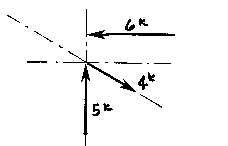
More than two non-parallel forces can be combined by successively eliminating one of the forces. Combine any two of the forces into their resultant by the parallelogram method. Combine this resultant with any of the remaining forces (or with the resultant of any of the remaining forces) until all of the forces are included. One must remember that the vectors can only be translated (or moved) along their lines of action. Two vectors (or Forces) cannot be combined (or resolved) until both of them are meeting head-to-head or tail-to-tail!
The resolution of the this system is a single vector that has a magnitude of approximately 4k with a direction of up and to the left. Try it yourself!!!
The Triangle of Forces Method is another graphical method developed to find the resultant of a coplanar force system. Since the opposite sides of a parallelogram are equal, a force triangle may also be found instead of using the parallelogram method. This method is quite useful because it can be successivly applied to any number of concurrent forces.

To calculate the resultant of the force system shown above, move force A
so that it's tail meets the head of force B. Now forces A and B form a "Head-to-Tail"
arrangement. The resultant R is found by starting at the tail of B (the
point of intersection of forces A and B) and drawing a vector which terminates
at the head of the transposed A. Note that if force B had been transposed
instead of force A, the resultant would have started from the tail of A
and terminated at the head of force B. Again, this process could be repeated
for any number of force vectors.
The resultant is described by the vector's magnitude and direction. These are determined by scaling the length and angle respectively. The accuracy of these values depends upon the accuracy of the graphics.
More than two non-parallel, non-concurrent forces can be combined by successively eliminating one of the forces. Combine any two of the forces into their resultant by the triangle method, and then extend that resultant until it intersects the line of action of another force. One continues this process until all forces have been included. In this way, each one of the forces is successivly combined with the resultant of the previous triangle. One cannot simply continue to add the vectors head-to-head or tail-to-tail because the resulting lines of action would then be incorrect!
![]() Animation illustrating how to resolve vectors with the
Triangle method
Animation illustrating how to resolve vectors with the
Triangle method

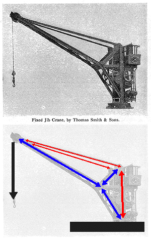
This illustration of a fixed jib crane allows one to read the forces
as they meet at the tip of the boom. The diagram indicates the forces acting
in the crane: red for tension and blue for compression.
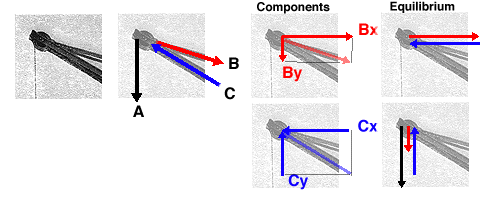
The graphical methods of force decomposition could be used to determine
the magnitude of the forces within the crane. In this case the two components
for each of the structural elements are shown. All of the vectors are representational.
They are not drawn to scale. The actual magnitudes are simply determined
IF one would actually draw ALL of the vectors to scale and then measure
the results.
![]() A
Thrust on a Wall
A
Thrust on a Wall
![]() A
Comparison of the two methods
A
Comparison of the two methods
Could one determine components that are not related to the x and y axis for the crane? why might one need to do this?
For those who are interested in reading more about graphic statics: