Prior to being assigned the challenge, we were given real-life applications for concepts like hill climbing, tilting, centor of gravity, etc, that we may need for our robot. We then built the gameboard we were going to use for the competition. This board had multiple tasks that could be executed with varying points.
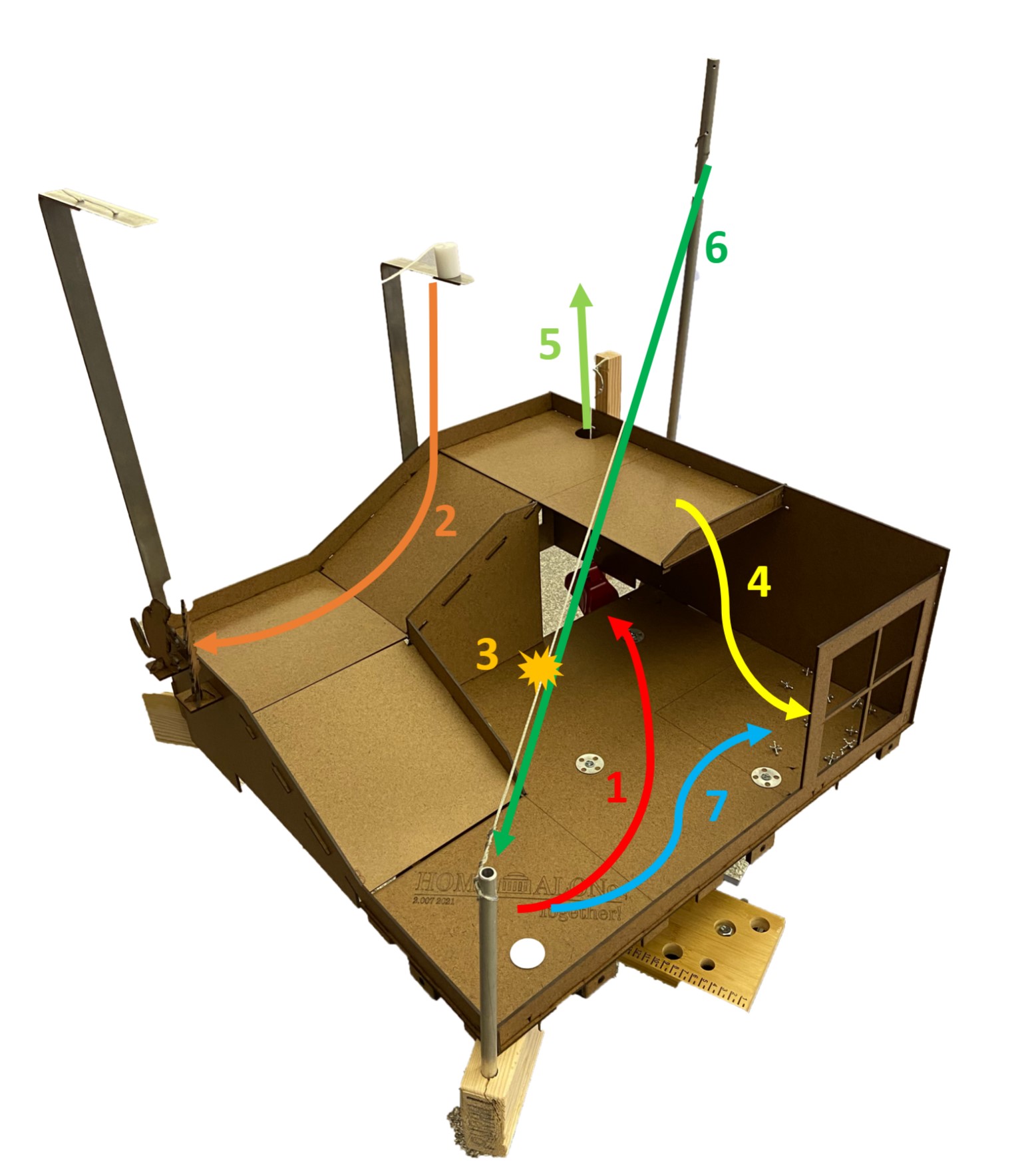
- Push down the robbers into the basement.
- Knock down the paint cans + knock down the robbers with the cans.
- Cut the zipline.
- Lift and dump jacks from top floor to first floor corner.
- Pull bell to multiply points (marks distinct levels).
- Ride down the zipline fromt the top to the first floor.
- Make noise with the noisemaker.
To begin my brainstorming, I reviewed all of the rules and constraints to determine what path was best to spend my 90 seconds of gameplay of the competition. I printed multiple pictures of the gameboard and drew my own path of tasks, while estimating the amount of time it would take to do them. I believed choosing a path would break down the challenge into specific designs I'd need to address with my robot. I spent quite a bit a time, and you can see some of my initial thoughts and considerations here.
From my initial strategies, I narrowed it down to one by a decision matrix. I had many criteria, such as feasibility, time constraints, level of difficulty, functionality, resource constraints, points awarded, etc. I chose to cut the zipline from the highest height possible and have the robbers attached to it to knock them down. I selected this because of the points, but also the fact that this challenge greatly differed from all the others and that it has an entertaining factor to it. I listed out my design requirement list that was quantitatively specific with height, weight, and speed of the robot. I created numerous concepts to complete this task from a slingshot to scissor lift to a 4-bar linkage.
For my prototype, I focused on my most critical module (MCM) to assure that my critical component would perform properly in time before the competition. I determined that what was critical for me was to (a) reach the tallest height of the zipline and (b) cut it. I would focus on the affects of the MCM's weight distribution on my chasis for hill climbing later on.
To begin with, I created a base chasis to hold my MCM and push some robbers into the basement. I'd use this base for not only MCM support, but as a back up robot to push robbers and jacks to get points.
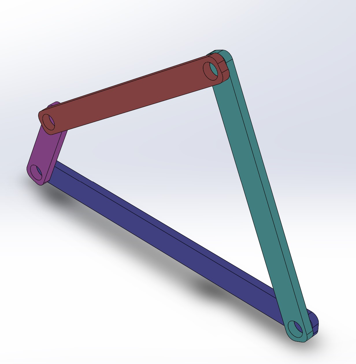
I used foamcore and screws/nuts to prototype different linkages to achieve the desired height, as well as CAD to visualize it. I also prototyped different holds for the blade to cut the zipline with foamcore. I had an extra blade from a cutting knife in my materials, so I chose this as my cutting mechanism due to simplicity and effectiveness.

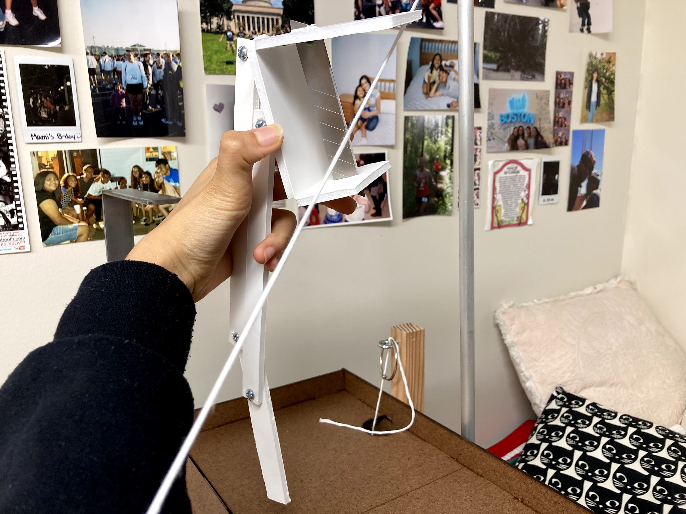
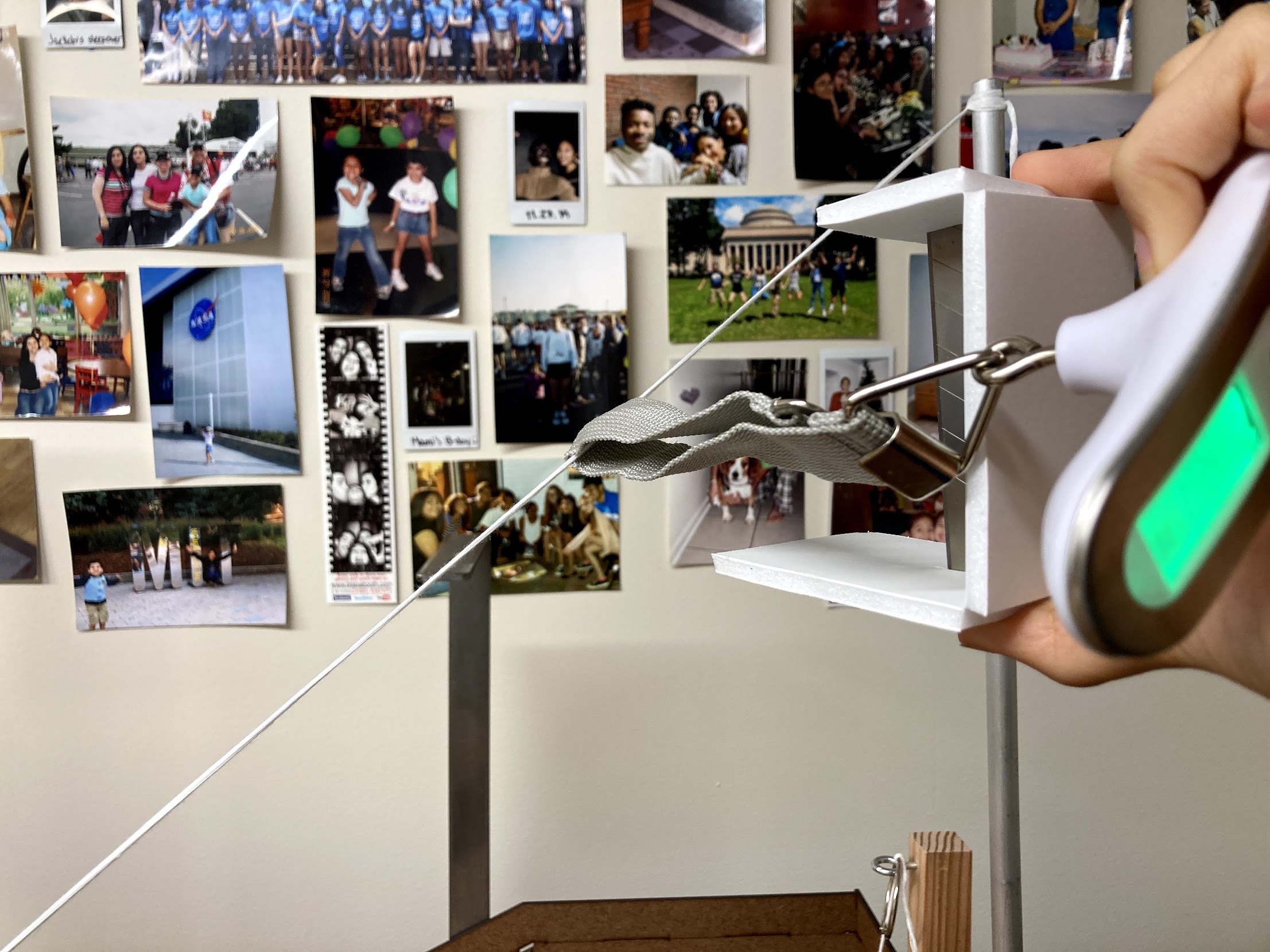
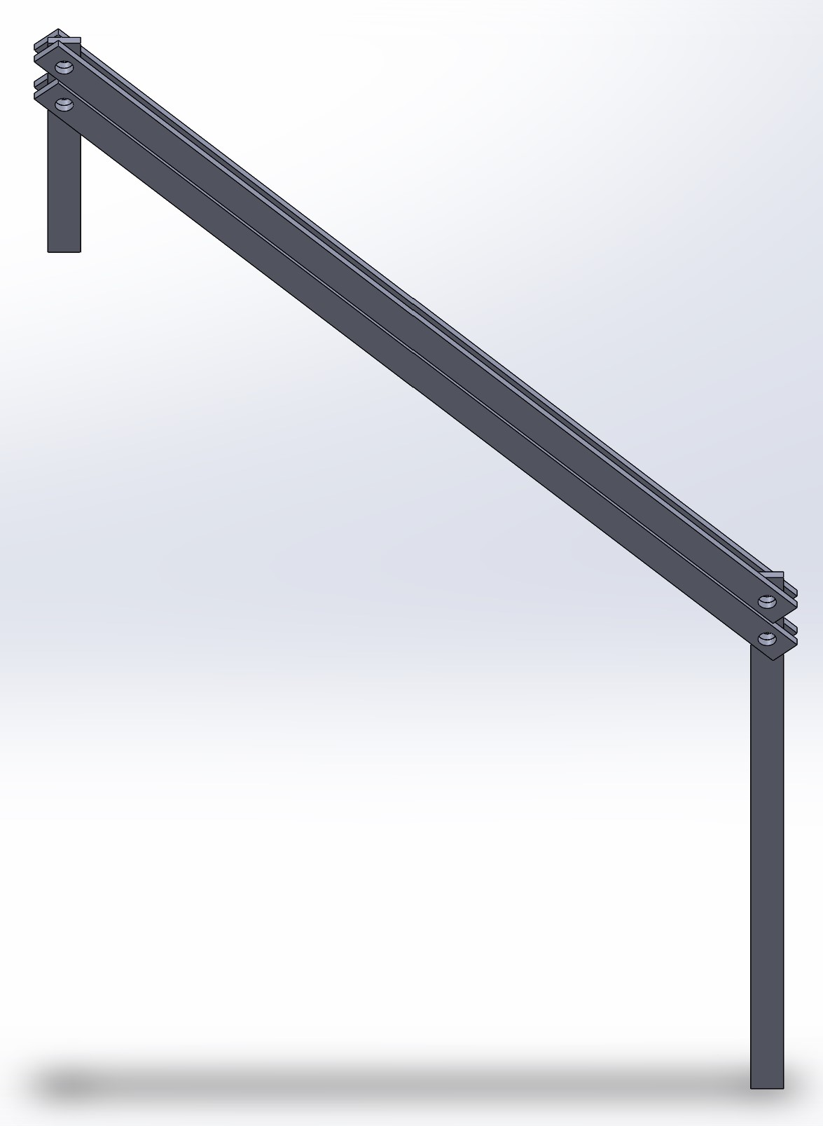
I also tinkered with Arduino to climb up to the top of the gameboard. I didn't use this with my final robot, but it was valuable to learn.
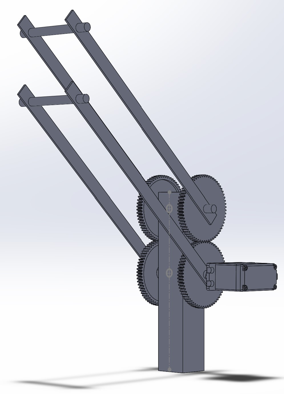
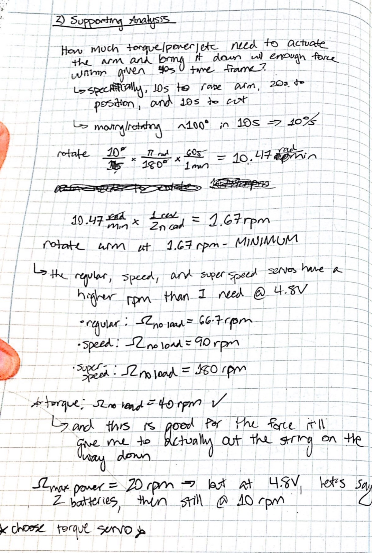
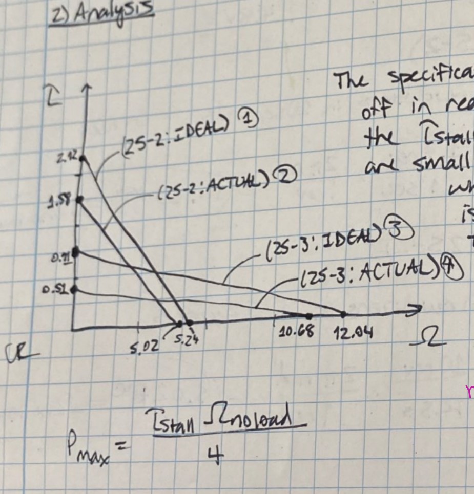
An additional thing I needed to consider was how I planned to move the linkage on my MCM. Based on torque and force calculations, I chose to go with the torque servo over the speed servo. I wanted to place the servo closer to the chasis, as it was heavy and would cause the robot to tip over more easily when climbing. The problem here was that I then wouldn't be able to achieve the 14.5 inch height. My method to address this was to use gears to translate this movement to my linkage. I planned to use a hallow aluminum rod to be placed on top of my chasis. I would then create aluminum shafts to attach my gears and torque servo to. Finally, I can add the linkage to the top portion of the aluminum bar in order to have it reach the height once extended.
The first thing I built was the chasis. I used aluminum sheet metal to create this using a variety of tools. It was a success when going up the staircase on its own. This took me nearly 3 hours to build, as cutting, bending, and drilling the metal took quite some time to be done correctly. Making this robot was also useful practice for testing out the controls on my RC controller.
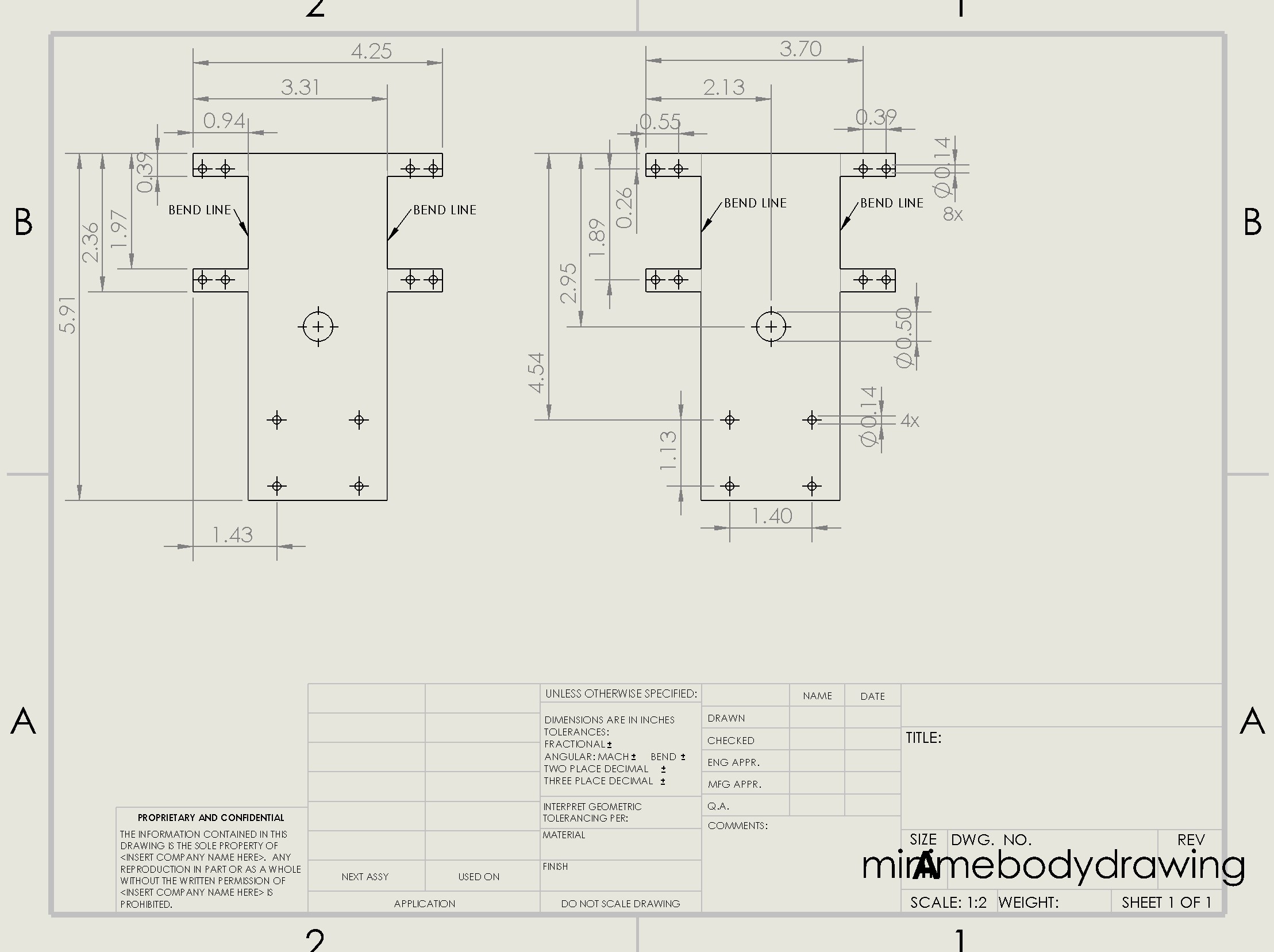
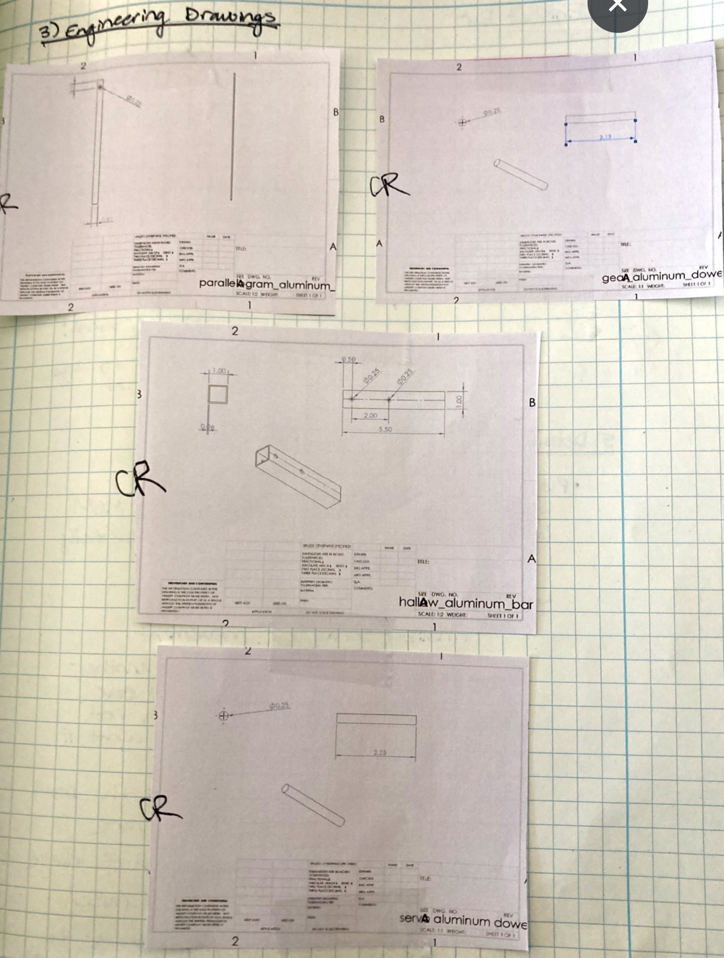
When beginning my MCM build, I created all of my main components first (ie. hallow aluminum rod, aluminum shafts, etc). This is shown in the engineering drawings below.
I then created my knife hold and assembled my MCM together. Finally, I attached this onto my chasis. What I learned from this is that I needed something to support the weight of my torque servo. To address this, I devised a masonite mount that would attach to the servo and then to the chasis by an aluminum bracket. I chose masonite as my material because it was lighter weight than the metal, which would make it easier to balance the moment balance of the robot (so it won't topple over on its side).
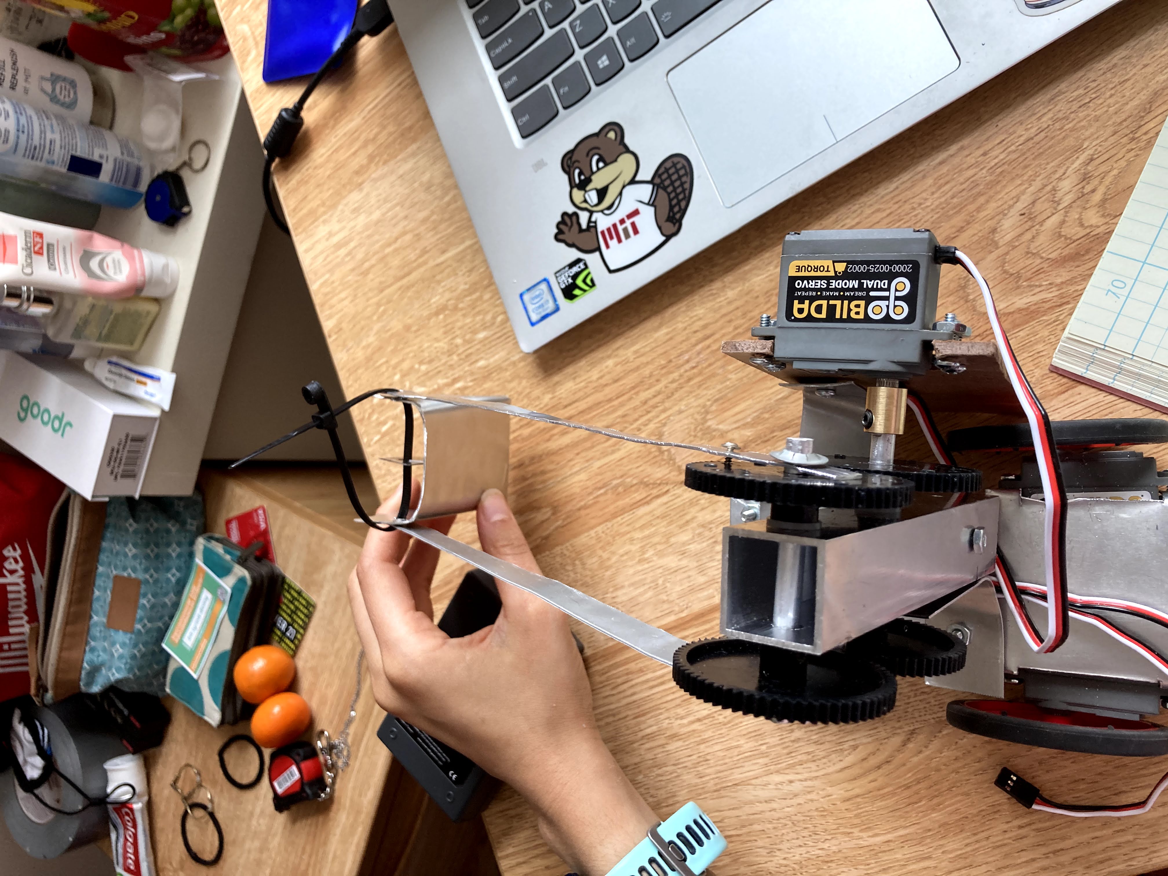
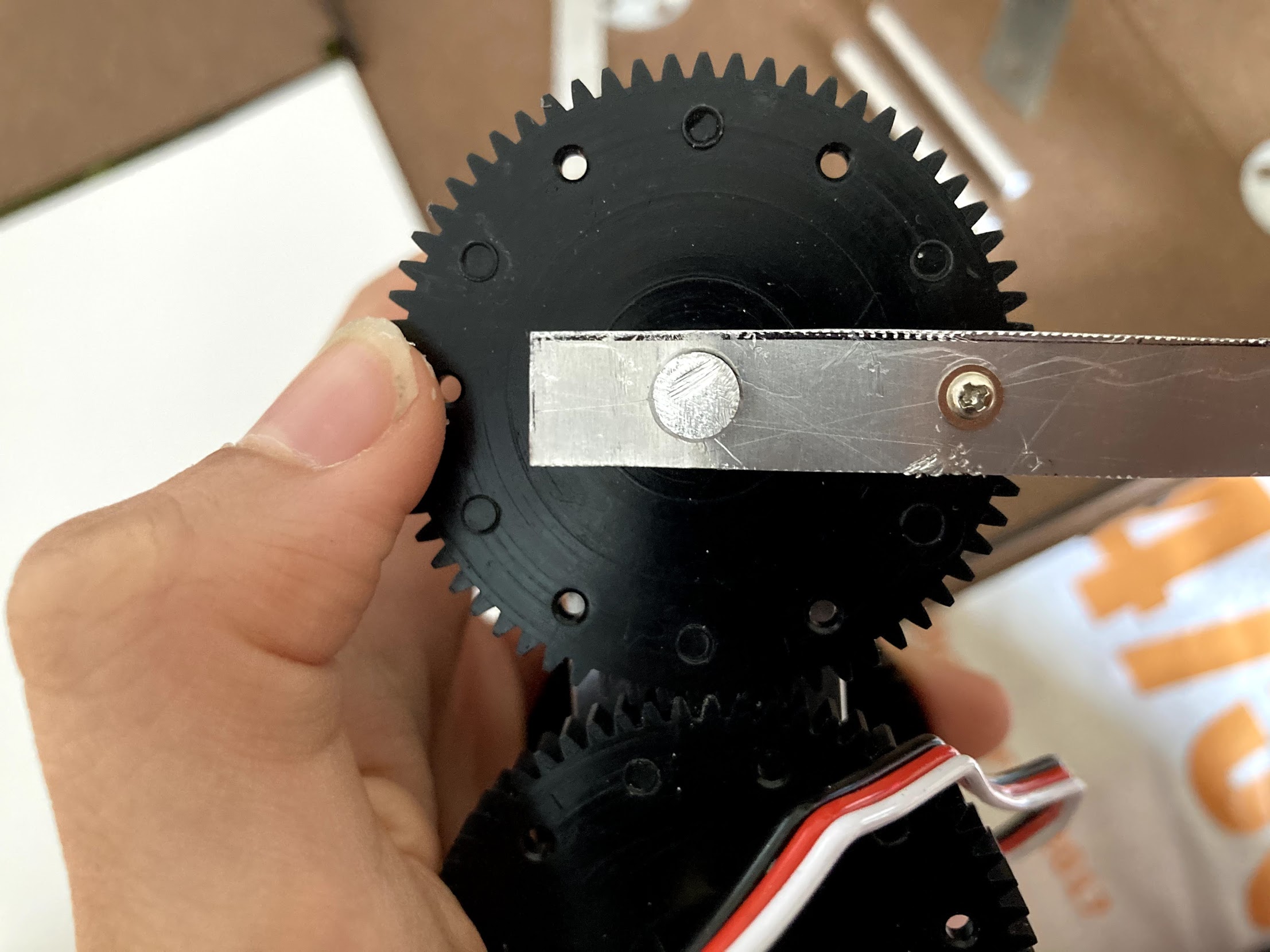
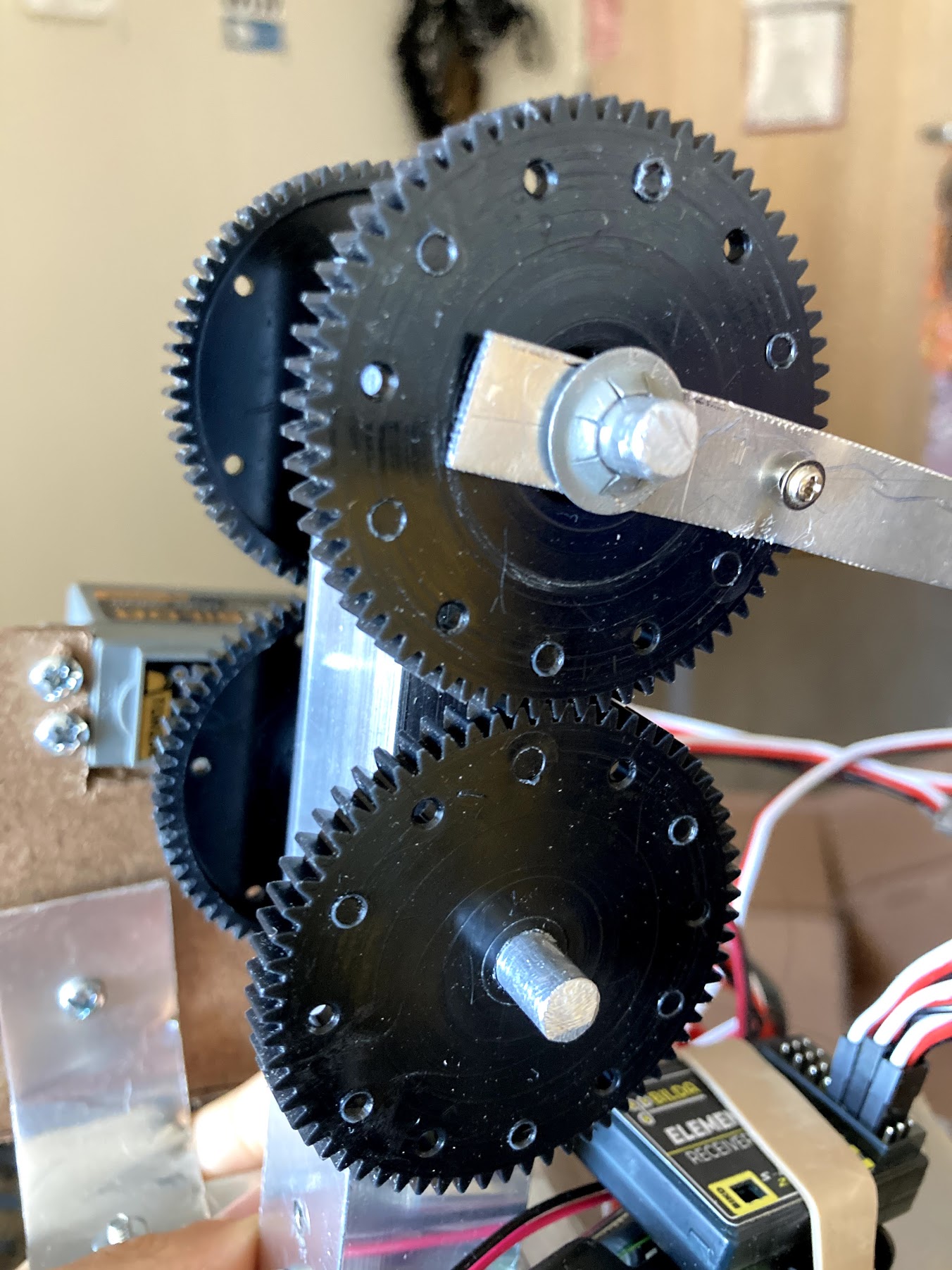
Manufacturing the robot came with a lot of time and patience. I sometimes would spend hours on something, and it wouldn't even work properly. One example was the way in which I meshed the gears together. There are so many components factoring into the success of the gears meshing properly: the holes drilled into the hallow aluminum bar were drilled the exact distance apart, the shafts were not slanted in any way when going through the hallow bar, and when the gears were meshed they weren't too tight so as not to move or too loose. The issue I dealt with was alignment of these gears when they meshed. They were WAY TOO close to one another, so the friction against each other prevented them from moving at all. This led to my gears being misaligned since this way they could sort of move. Look at this below.
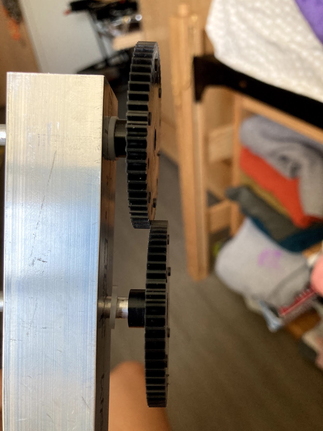
Moreover, besides the time it took to make my parts correctly, I also came up with many tricks to manufacture things faster while not degrading the quality of my component. I essentially improvised with the tools I had. For instance, I used my drill as a lathe for my aluminum shafts. Althought the holes I drilled into the hallow aluminum bar were the same diameter as the aluminum shafts, most times the shafts wouldn't go through. What I did was then "lathe" the ends of the shaft to add some curvature so it could slip into the holes I drilled.
I didn't have much success with cutting the zipline using this prototype, however, I did easily reach the target height of the zipline. From this, I needed to come up with a better way to get the knife to more easily cut the string. My current issue was that the holder would swing too much when I'd drive into the string. To resolve this I chose to use only when extended aluminum bar to reach the height and attach the blade to its side with screws and nuts. This worked flawlessly because the blade itself had a hole in it, so I drilled a hole into the bar to attach the two. The existing hole on the blade was at one end of it. I was going to drill another at the other end but the blade gave in and broke, hence why I used the zip tie to hold it up.
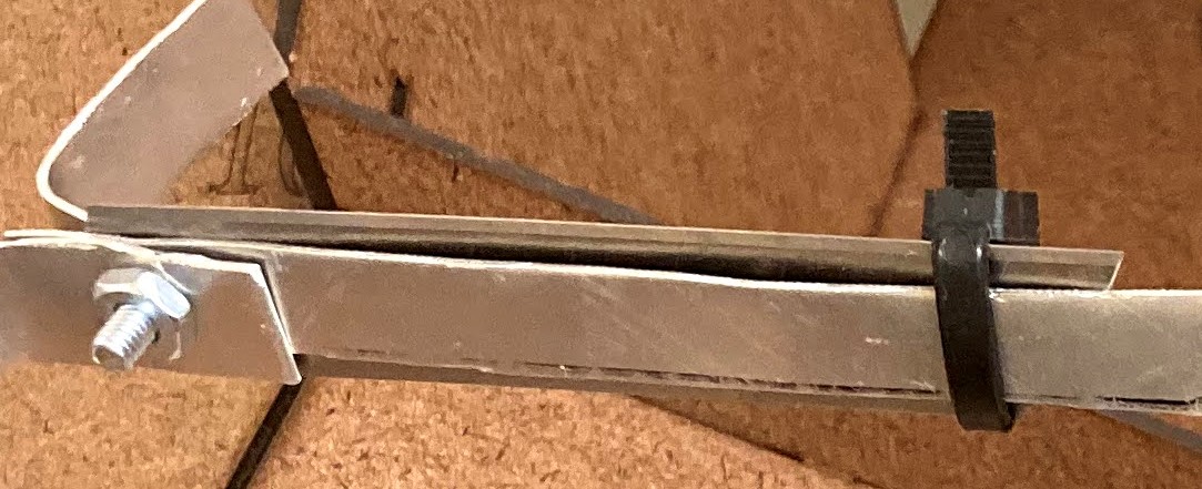
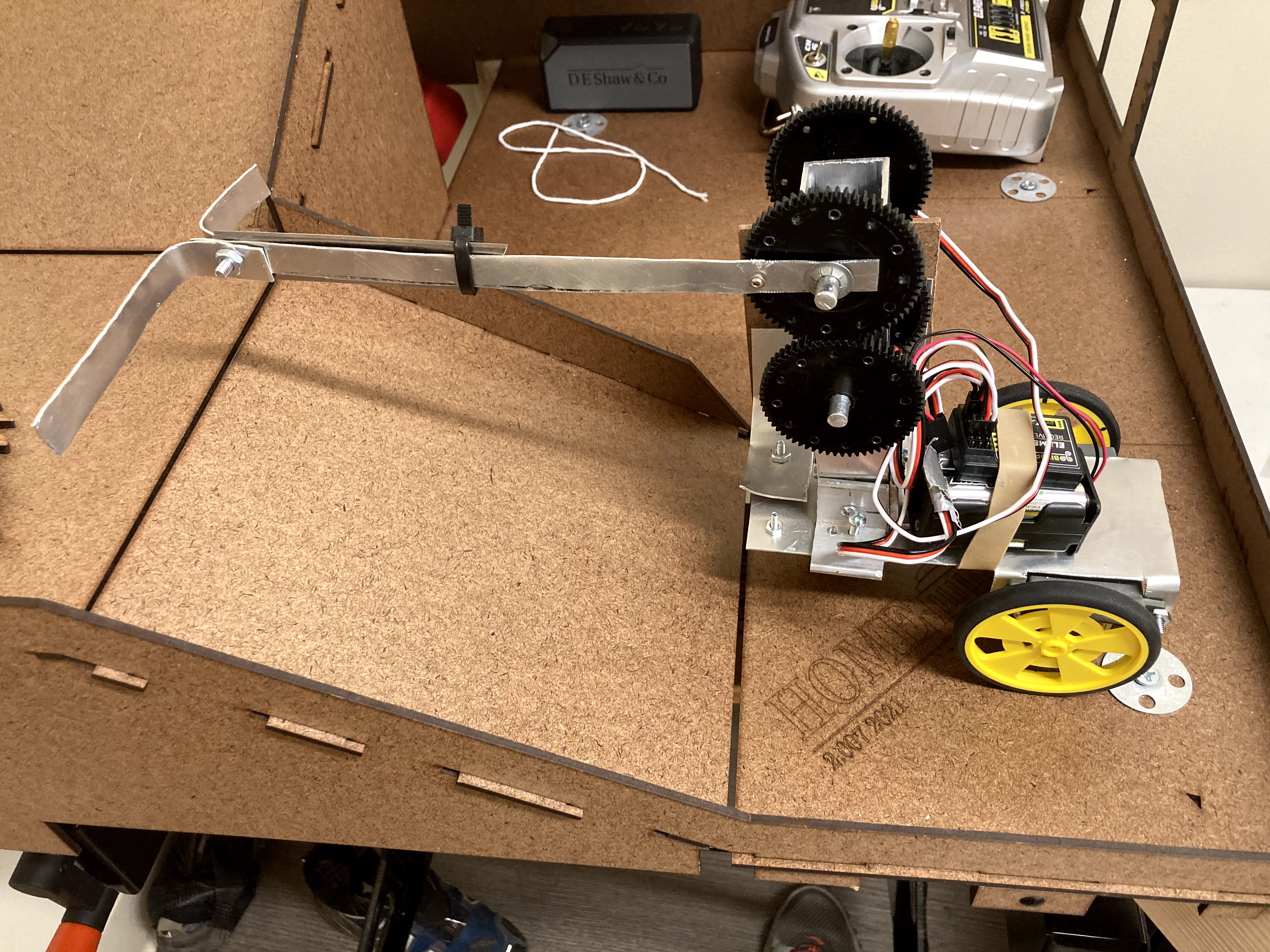
Besides the blade upgrade, I chose to have one aluminum bar rather than two like before. I did this for simplicity, as well as for a balanced moment balance of the robot. This arm and blade were placed on the opposite side of the torque servo and masonite mount.
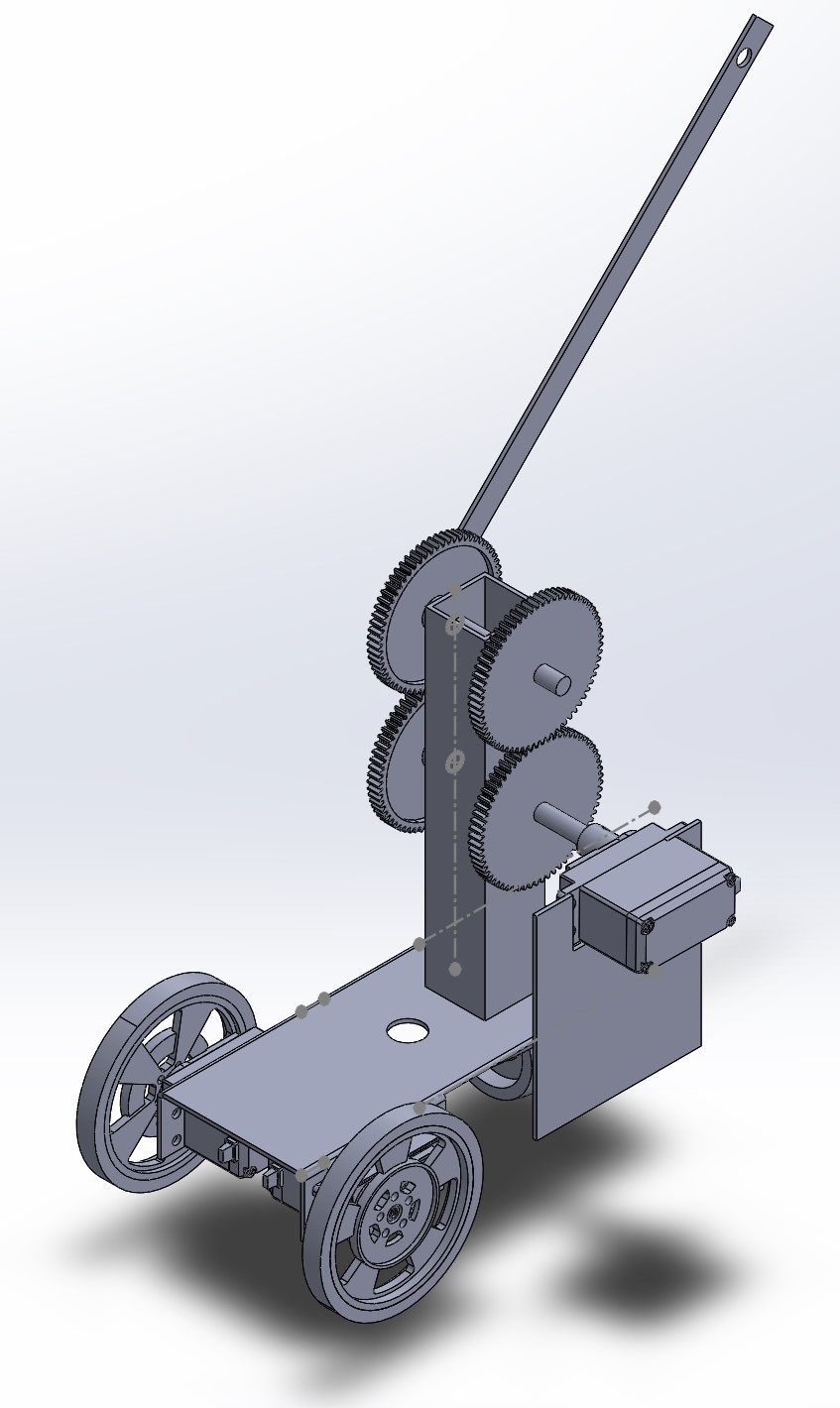
I manufactured my shafts and hallow aluminum bar again to assure that my gears were meshed properly. I took a lot of time and learn tricks with the step drill bit in order to get the holes drilled on both sides of the hallow bar in a straight line. Taking the time to do this precisely how I needed to do it was just what I needed to have a successfully moving MCM. Another trick that I did to save time without giving up functionality of the gears was by only making my bottom shaft (the one with the torque servo) "alive". I did this by inserting a tension pin through the gear and the shaft, as show below.
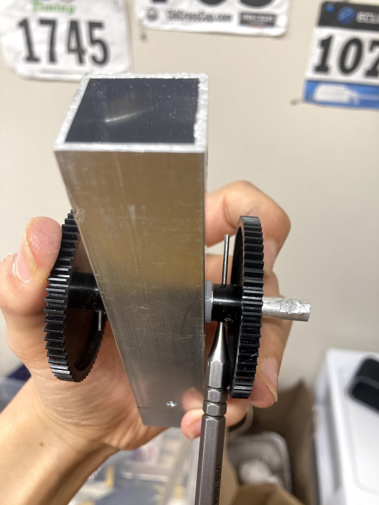
I then added a screw and nut through the end of the top gear to the extending aluminum bar. This way, the bottom "alive" shaft would turn, which would then turn the top gear that was attached to the bar. Because the top gear will always turn due to the bottom gear, then it didn't matter if the shaft was "dead" or "alive". All in all, the gear meshed perfectly, and I had great success with ataching the bar to the top gear.
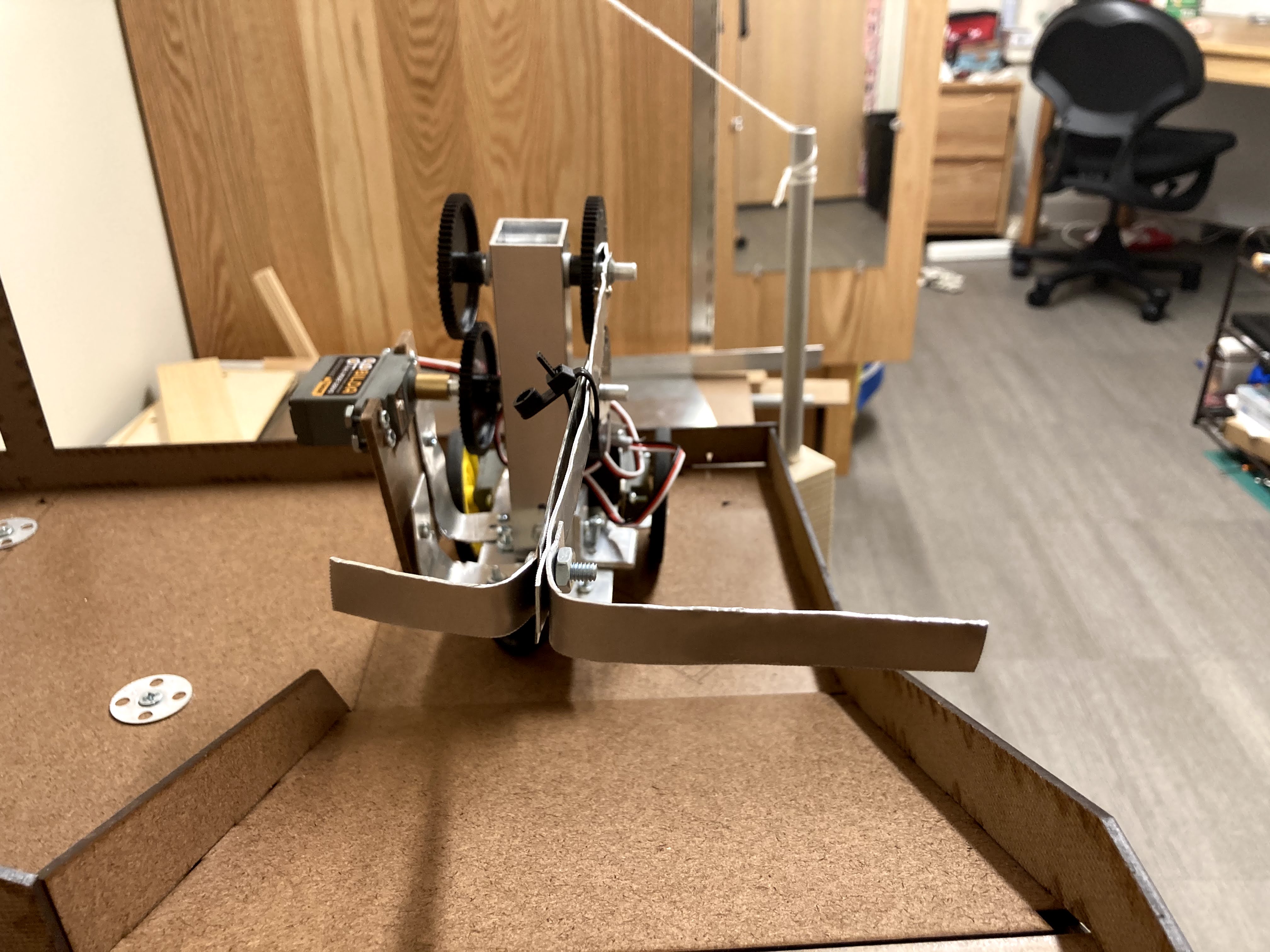
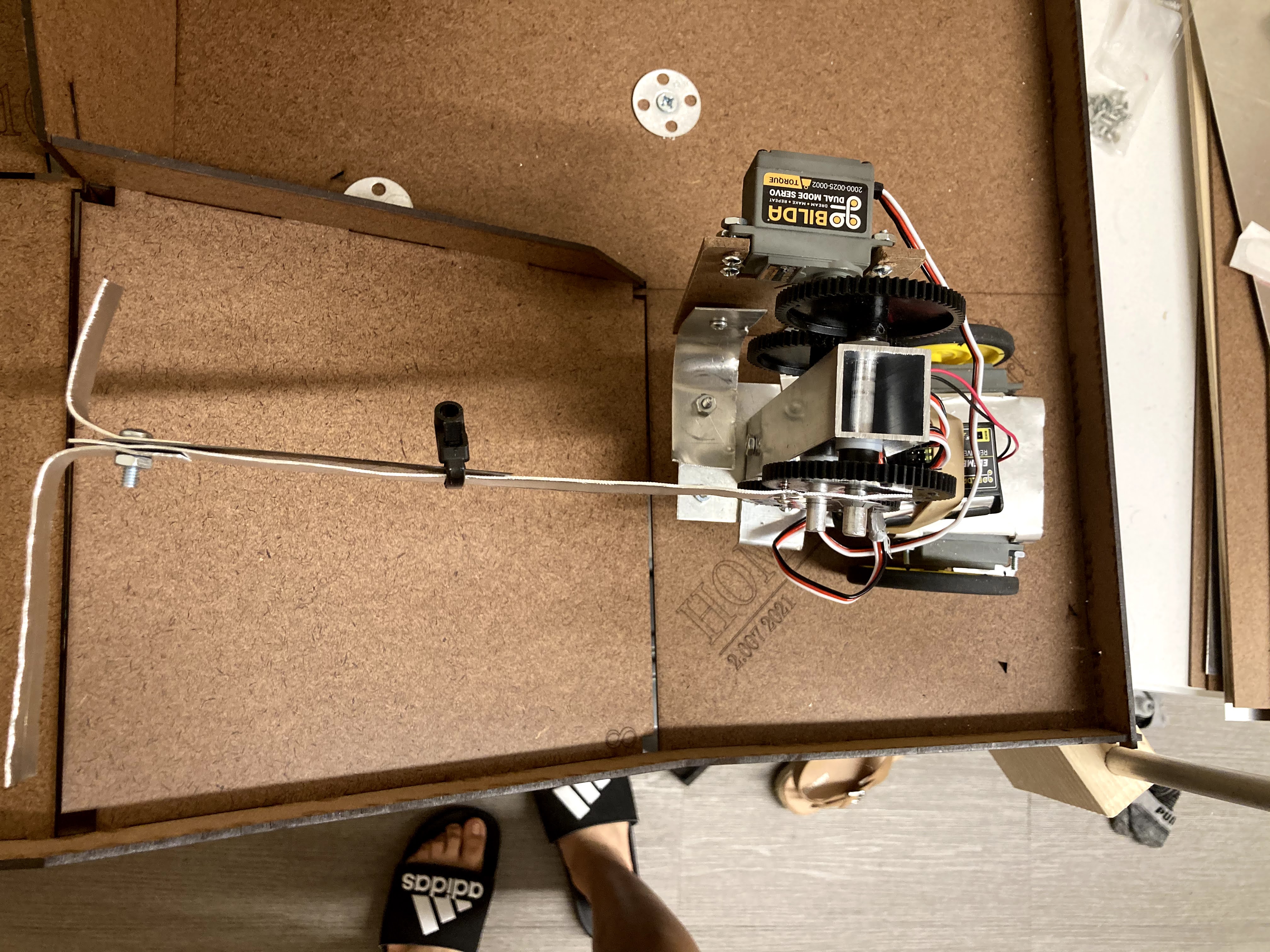
Last-minute addition: aluminum bent bars near the blade. I added these last components because I realized that my MCM reaches past the height needed to knock over the paint cans. So as another effort to gain more points, I chose to include this quick addition for more points.
My final robot was composed of: my chasis, torque servo and masonite mount, aluminum brackets, gear transmission, attached blade, and aluminum bent bars near the blade. During the competition I scored 15 points from knocking one of the paint cans down and having it hit both of the robbers with it (7 + 4 + 4). Unfortunately, I wasn't able to complete my original plan because after I knocked down one of the paint cans, my wheel got caught with the string. This was due to the fact that I didn't drive fast enough up the ramp that when the paint can swung back, the can went on the underside of my robot and the string got caught. It was an input error on my part on the controller, but I still feel proud of what I was able to make.
I am astounded on how I was able to brainstorm, design, and manufacture a robot from scratch. I was able to have a lot of building and design experience from this project, along with a ton of fun. This class has been one of my favorite course here at MIT by date. Mind and hand, our university's motto, could not have been more true as it was in this class.

return to projects page