
Study of the Temperature Microsensors for Possible Applications in the UDS Process
By
Paul Pao-Hua Chai
Submitted to the Department of Mechanical Engineering
In Partial Fulfillment of the Requirements for the Degree of
Bachelor of Science in Mechanical Engineering
At the
Massachusetts Institute of Technology
June 1999
© 1999 Massachusetts institute of Technology
All rights reserved
Signature of Author _______________________________________________________
Department of Mechanical Engineering
April 20, 1999
Certified by _____________________________________________________________
Jung-Hoon Chun
Associate Professor of Mechanical Engineering
Thesis Advisor
Accepted by _____________________________________________________________
Ernest G. Cravalho
Professor of Mechanical Engineering
Chairman, Undergraduate Thesis Committee
Study of the Temperature Microsensors for
Possible Applications in the UDS Process
By
Paul Pao-Hua Chai
Submitted to the Department of Mechanical Engineering
on May 7, 1999 in Partial Fulfillment of the
Requirements for the Degree of Bachelor of Science in
Mechanical Engineering
ABSTRACT
In this study, the behavior of a temperature sensor design for the UDS process is thoroughly studied. The sensor has shown a lot of promise to experimentally measure the transient and spatial temperature behavior of the molten metal droplets.
However, experiments of the temperature sensor inside the UDS system have resulted in failures because of random and unstable behaviors the sensor exhibit when inside the enclosed UDS chamber. Subsequent experiments to test the stability of the sensor in different environments and conditions proved the sensor to be unstable in various conditions. The resistance of the sensor is affected by the amount of current passing through the circuit, at higher currents, the sensor exhibits a lower resistance. When the current running through the circuit exceeds a limit, electro-migration effects may occur which cause permanent changes in sensor resistance. Because of the semi-conductor qualities of the sensing material, the sensor also exhibits photo-sensitive effects which caused change in resistance at the absence of light.
It is still possible to implement the sensor in the UDS system, but the following changes have to be implemented.
Thesis Advisor: Jung-Hoon Chun
Title: Associate Professor of Mechanical Engineering
Acknowledgments
First of all, I want to thank Professor Jung-Hoon Chun for his support and guidance as well as patience with me. His continual guidance and advice have been invaluable to me. I also want to thank Professor Tai-qing Qiu for his advice on the temperature sensor design and possible areas of concern.
Many thanks also to everyone in the DBM lab: Jeanie Cherng, Ho-Young Kim, Tasos Karahalios, Juan-Carlos Rocha, Wayne Hsiao, and Jason Barnwell for all the help and support. Especially for Jeanie Cherng and Ho-Young Kim, who have guided me toward my thesis work.
I also thank all my special friends for their encouragement through this year and throughout my college career. Finally, I thank my mother, Pearl Tien, and my brother, Edward, for their love and support all through my life.
TABLE OF CONTENTS
ABSTRACT 2
Chapter 1 Introduction 5
1.1 Overview of Study 5
1.2 Motivation and Objective of Study 5
1.3 Overview of the Thesis 6
Chapter 2 Background 7
2.1 The UDS process and apparatus 7
2.2 Thermodynamic Modeling of the Droplets 8
2.3 Other experimental Studies 9
Chapter 3 Temperature Microsensor 10
3.1 Design and fabrication of the sensor 10
3.2 Validation of the Sensor 11
3.3 Experimental Setup and Procedure 14
Chapter 4 Results and Discussion 17
4.1 Stability of the Sensor 17
4.2 Sensor Experiment with Boiling Water Droplets 20
4.3 Discussion of Results 22
Chapter 5 Conclusion 25
BIBLIOGRAPHY 27
Overview of StudyThe Droplet-Based Manufacturing (DBM) Process is based on metal droplet deposition. Its applications include spray forming, thermal spraying, rapid prototyping, and electronics packaging. In order to improve the quality of products made by the DBM process, the understanding of droplet deposition is fundamental, because it determines geometric definition, such as surface porosity and conformity to the substrate shapes, and mechanical properties of the deposit.
One of the crucial areas to study in droplet deposition is the thermodynamic behavior of the droplet upon contact with the substrate surface. Thermodynamic models for the droplets in flight and upon contact have been developed in theory, and attempts have been made to experimentally verify the model. However, as will be discussed in subsequent sections, the existing experimental methods have flaws, which result in uncertainties in regard to the accuracy of the measurements.
The conclusion from before stimulated interests in the possibility of implementing a new temperature microsensor design into the DBM process for more direct and accurate measurements. The objective of this thesis is, therefore, to test and verify the stability of the sensor and ultimately, to incorporate the sensor into the Uniform Droplet Spray (UDS) system to measure its thermal behaviors.
The general approach of the study is to first examine the stability of the sensor over time as well as in different experimental conditions. In order to measure and record the results, a data acquisition system is developed at the same time. The next step is to test the sensor as well as the data acquisition system with water droplets, and finally, to test the sensor inside the UDS system with molten tin droplets.
Chapter 1 presents the general overview of the study as well as the motivations behind. Chapter 2 gives a more detailed background on the UDS process, the thermal modeling of the droplets, as well as the existing experimental methods in measuring droplet temperature. In Chapter 3, the design and fabrication of the sensors and the experimental approach to test the sensor are both discussed. In Chapter 4, the results and measurements of the sensors are presented and discussed. The summary of this thesis is presented in Chapter 5.
The UDS Process and ApparatusDBM is a manufacturing process based on metal droplet deposition. In order to accurately control the quality of the product made by the process, it is essential to understand how process parameters such as the size of the droplets, velocity, flux, and thermal state affect the geometry and the microstructure of the deposit. It is very difficult to study such effects in conventional droplet spraying processes such as gas atomization and plasma spraying, because these processes tend to produce droplets in randomly distributed dynamic and thermal states.
The UDS process gives us a chance to study droplet deposition behaviors more closely by creating a spray of droplets with uniform size, velocity, and temperature. Since the end products of the process can be easily identified and characterized, it is possible to study the effects of various process parameters on the deposit quality by independently and precisely control individual parameters to produce desired products with greater accuracy.

Figure 1. A schematic diagram of UDS apparatus
The UDS apparatus contains a crucible with an orifice opening at the bottom, the metal subject is put in the crucible, which is then melted by a heater around the crucible, and ejected through the orifice opening with pressure applied from a gas supply. The ejected molten metal forms a laminar jet, which is vibrated by a piezoelectric transducer at a controlled frequency. The disturbance due to the vibration grows until the jet breaks up into a stream of uniform droplets, which is charged by a DC voltage charging plate. The charging of the droplets prevented the droplets from merging with each other in flight since the droplets would repel each other. The magnitude of the electrical charge can be controlled to change the trajectory and mass flux of the droplet spray. The charged droplets are then deposited on the designated substrate, whose temperature and material property can be controlled to affect droplet deposition geometry and microstructure. A figure of the UDS scheme is shown in Figure 1.
Thermal Modeling of the DropletsTheoretical models for the thermal behaviors of molten metal droplets have been developed before sufficient experiments have been conducted to verify the models. Most theoretical models have made general assumptions on the parameters that are difficult to determine, and therefore, it is crucial to validate the models with experimental data. Because of the complexities and difficulties in conducting these experiments, there have not been sufficient experimental data to fully back up the theoretical models.
Several numerical models have been developed to simulate impact and solidification of molten droplets on a cold surface. Studies have been done on droplet deposition assuming solidification starts after spreading by Bennett and Poulikakos and Kang et al (1994). Zhao et al. (1996) studied heat transfer and fluid dynamics of liquid droplet on a substrate in the case with no solidification. Other models and approaches have also been done: these include the use of finite difference models to study the simultaneous spreading and solidification of impacting droplets (Trapaga et al.1992 and Bertagnolli et al., 1995), and the effects of varying thermal contact resistance between the droplet and substrate to show that its magnitude can influence droplet spreading (Pasandideh-Fard and Mostaghimi, 1996), among other studies.
According to Pasandideh-Fard et al.(1998), however, in most of the numerical models, the substrates were assumed to be isothermal, thermal contact resistance at the liquid-solid interface was neglected, and the liquid-solid contact angle were generally assigned to be an arbitrary value. To date, only a few studies have been done to validate the numerical models rigorously by comparing with experimental results. Some of the reasons include the scarcity of experimental data, and the difficulties in analyzing the physical parameters of the substrates. As mentioned previously, the value of the thermal contact resistance as well as the liquid-solid contact angle can drastically change the behavior of deposits. The conclusion from the Pasandideh-Fard et al. studies showed that theoretical modeling of the thermal behaviors of the molten metal droplets can provide reasonable predictions to the experimental values only when the value for the thermal contact resistance is accurately estimated.
There are several different attempts in trying to experimentally measure droplet thermal properties, most of them can be generalized as trying to catch the droplet in flight and indirectly determining its properties. One such experiment involved the quenching of Al-Fe alloy droplets at varied flight distance with silicone oil, and the microstructure of the quenched powders were analyzed in developing a model for solidification of droplets. (Cherng, Chun, and Ando, 1998) Another method, which is called non-adiabatic calorimetry, involves collecting droplets in oil-filled calorimeter and measuring the change in enthalpy within the system in determining the thermal state of the droplet. (Truffile, Ando, and Chun, 1998)
There are several drawbacks to the methods describe previously. The non-adiabatic calorimetry involves measuring the enthalpy change of the calorimeter rather than directly measuring that of the droplet. This method is indirect, and the margin of error is large because of excess heat loss from the system that cannot be measured. It is not easy to account for the evaporation of the oil or additional heat loss to the environment. Difficulties caused by droplet splashing also provide a source for large errors. As for quenching, again, the thermal behavior of the droplets is derived based on the analysis of the microstructure of solidified droplets, and the measurement is not direct. Direct measurements are very difficult to implement, but there have been attempts, though not quite so successful, to spray directly onto the tip of thermocouples. (Mathur, Apelian, and Lawley, 1989) A caloric probe designed by Fischer and Kozarek (1998) was also tested, while showing some promises, the accuracy of the results were hampered by a number of factors including heat loss to the surrounding and the design of the probe dimensions.
Chapter 3 Temperature Microsensor
Design and Fabrication of the SensorThe temperature microsensor is deemed as one possible option to measure the thermal state of spreading droplets. The sensor is designed with conductive aluminum lines lying in parallel on top of a boron-doped silicon pad to create an array of sensors. The coarse resolution sensors are spaced 200 microns apart in a one-dimensional parallel array, while the fine resolution sensors are spaced 50 microns apart from each other in a two-dimensional array. The sensing area for each sensor is made of 2 m m by 2 m m lower boron-doped poly-silicon that is surrounded by higher doped poly-silicon material on the pad. The layout of the sensor scheme is shown in Figure 2.
 The design of the sensor is based on the Resistive Temperature Detection (RTD) concept to measure the impact temperature of the droplets. The choice of boron-doped silicon as the sensing material is based on its rapid response in transmitting electric signals, which would be ideal for the UDS process since the droplets solidify in the time frame of only tens of micro-seconds upon contact with the substrate. The spacing of the aluminum lines is designed to measure the spatial as well as the transient temperature profile of the molten metal droplets. Based on the properties of the sensing material, resistance decreases exponentially as temperature increases and vice versa.
The sensor would be an ideal candidate to measure the thermal states of the droplets in the UDS system for a few reasons. The measurement is more direct since the droplets are directly touching the sensor, and the resistance of the sensor is measured in situ because of the rapid response of poly-silicon to electric signals. The sensing area is very small, which would minimize heat loss in the system and provide more accurate results.
In order to use the sensor for measurement purposes in the UDS process, the sensor has to be calibrated first. Calibration work has been done to determine the inverse relationship between sensor resistance and temperature. The sensor chips are placed in temperature-controlled quartz-tube furnace and the temperature inside the furnace is cycled from room temperature to about 250oC. Thermocouples are connected to the sensor to correlate the actual temperature to the sensor output, and a voltage divider circuit is used to convert the resistance of the sensor into voltage, which can then be measured by the data acquisition board. The experimental setup for the calibration is shown in Figure 3 below:

Figure 3 Sensor Calibration Scheme
From the calibration experiments, it would be possible to determine the relationship of the sensor’s electrical resistance as a function of temperature. The sensitivity of boron-doped silicon was originally predicted to be about 0.7% /K, after the calibration experiments, it is shown that the resistance decrease exponentially with temperature at an average rate of 0.9 % /K, independent of the its initial resistance. Some typical calibration curves of the relationship between temperature and resistance is shown as follows:
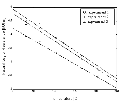
Figure 4. Calibration curves of sensor
LabView software is chosen to be implemented as the data acquisition system because of its capabilities to: (1) program multiple purpose measurement instruments, (2) scan at a rapid sampling rate of close to 1 million scans per second, and (3) capture and store data in the computer in spreadsheet format. LabView data acquisition system contains a data acquisition chip and board, which take voltage inputs, process and display readings on the computer screen. A virtual instrument program is constructed in LabView for the special purpose of this study as it triggers on a sudden change of voltage, captures data in a rapid scanning rate, and records data in the form of spreadsheet format.
A voltage divider circuit is constructed to convert sensor resistance into voltage, and in order to reduce ambient noise from the sensor, the sensor is connected to the circuit through a high pass filter. Inside the voltage divider circuit, the sensor, which by itself a resistor, is connected in series with another resistor of comparable resistance. The voltage divider circuit is shown in Figure 5.
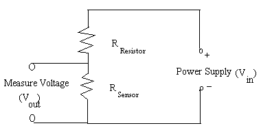
Figure 5. Voltage Divider Circuit
The output voltage from the circuit that is displayed on the computer is equal to:
 (3.1)
(3.1)
Therefore, as the resistance of the sensor increases, the output voltage increases, and so on. In order to ease the calculation and measurement of sensor resistance, the resistor used in the experimental setup is adjusted to be equal to the initial resistance of the sensor. The initial output voltage would be equal to ½ of the input voltage as the result.
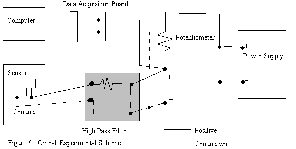 The experimental setup has the LabView data acquisition board connected to the circuit to measure the voltage across the sensor. A HP DC power supply is used to supply a constant input voltage of 0.5V and variable current between 1mA to 3 mA across the circuit. Initial resistance of the sensor is first measured by a ohmmeter, and a potentiometer, adjusted to the same initial resistance, is then used as the resistor in the circuit. The experimental scheme is shown in Figure 6.
The initial attempts of implementing the sensor inside the UDS setup have resulted in various failures. The resistance of the sensor became unstable when it is enclosed inside the UDS chamber, fluctuations of up to 50% were observed on the resistance value. The initial failures have raised questions in regard to the stability of the sensor, and in consequence, experiments are conducted to measure the resistance of the sensor over time as well as in different physical conditions.
In order to measure the transient response of the sensor to a droplet, experiments are also conducted in which the proposed experimental setup is tested by dropping boiling water droplets on the sensor. The ultimate goal is to verify the stability of the sensor and then to apply the sensor in the UDS system.
Chapter 4 Results and Discussion
Stability of the SensorExperiments were run initially to test the resistance of the temperature sensor over time to see if the resistance of the sensor stays stable in a prolonged period of time. The results are very convincing as most of the sensors have stable resistance over a long period of time with small fluctuations, which reflect temperature changes.
The next step is to examine the behavior of the sensor when it is placed inside the UDS chamber. Surprisingly, the sensor exhibited random behaviors with such a change of environment. Some of the sensors stay stable in resistance or have minor fluctuations that are within 10% of its initial resistance. However, for some sensors, the resistances decrease sharply while other sensors have exhibited sharp increases in their resistances. It can be clearly seen in Figure 7, which shows the transient resistances of a chip with 8 sensors. The resistance values in the first 100 minutes are measured while the temperature sensors are placed in open-air room environment. Each unit of time frame is roughly 10 minutes apart. After 100 minutes, the chip with the sensors was placed inside the UDS chamber, and at the 140th minute, the chip is taken out of the chamber.
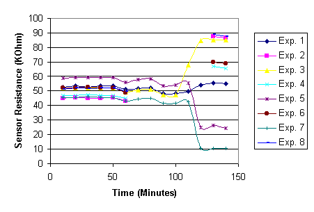 Figure 7 Sensor behavior at different times and environments
The results seem to suggest the change of environment from open-air to inside the UDS chamber cause irreversible shift of resistance on some of the sensors.
Another set of tests is run to see if the sensor stays stable after running it through electrical currents for a prolonged period of time. The sensors are connected directly to the power supply at 0.5V constant voltage and varied current between 1mA to 3mA, and after 5 minutes, the resistances are measured. As shown in Figure 8 between the 10th and 30th minutes, some of the sensors also seem to be affected by the charging of electric currents for 5 minutes, most of the sensors tested seem to exhibit an increase in resistances over prolonged time of charging. The resistance of the sensor is also measured after a protective mask made out of insulating film is put on top of the sensor. Surprisingly, the act of covering the sensors with a mask also induced an increasing trend of sensor resistance over time. (As shown in Figure 8 between the 50th minute and 100th 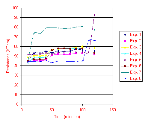 minute) Two sensors (Experiments 6 and 8 in Figure 8) are placed in the chamber after the mask test, and once again, their resistances increased drastically as shown.
Figure 8. Sensor response to charging, masking and chamber conditions
From the experimental results shown above, it is still uncertain of the true effects of the amount of electric current on the sensor value. To test the behavior of the sensor at different currents, the sensor is placed in the same voltage divider circuit as shown in the experimental setup.
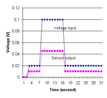 The power supply is turned on and different currents ran through the sensor and the circuit at first, 0.02 volts of charge for 5 seconds. The current is then increased to a charge of 0.1 volts for a period of time before shifting back to 0.02 volts. The voltage output of the sensor and the input voltage of the power supply over a period of 30 seconds are shown on Figure 9.
Figure 9. Effect of Different Electric Currents on Sensor Value
From the results, it is clear to note that as the amount of current increases, the resistance of the sensor actually decreases between voltages of 0.02 and 0.1 volts. The results are discussed in detail in subsequent discussion section.
Testing of the experimental setup with boiling water droplets has generated the anticipated response from the sensor. The transient response of the sensor is shown in Figures 10 and 11 for two different water droplets with different sizes.
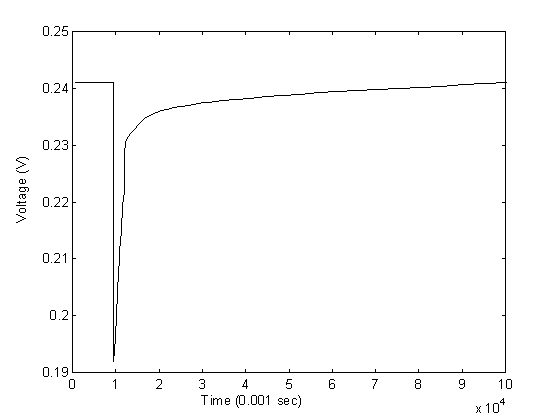
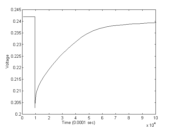
The initial resistance of the sensor in the above experiment is approximately 45 KW and the potentiometer is adjusted to the same resistance. The input voltage is at 0.5 volts which returns an output voltage of approximately 0.24 volts. From the figures of the two droplets, we observed an average drop of voltage by approximately 0.05 volts, or at 0.19 volts when the water first dropped on the sensor with the highest temperature. By back calculating the resistance of the sensor at the initial contact, the resistance at the initial contact is calculated to be approximately 28 KW . Assuming the sensitivity of the sensor is approximately 0.9 %/K as derived from the calibration experiments, the temperature of the water upon contact with the sensor is approximately 42oC. The result is very reasonable considering significant heat loss occur when pippet is applied to gather water from a pot of boiling water and then water droplet travels in air before finally touches the sensor.
The response from the sensor also showed first, a sharp decline of resistance and then, a gradual increase of resistance back to the original value. This also confirms with the physical phenomenon as the sensor experiences a sharp decline in resistance at the instant when the water droplet hits the surface causing a sharp increase in temperature. As time goes on, the water droplet gradually cools down to air temperature by mostly convection, and the resistance of the sensor gradually increases to reflect the increase in temperature.
From the results above, several generalizations can be made in regard to the temperature sensor and its behaviors.
From the observed behaviors of the sensor, some suggestions have been proposed which may or may not explain the random behavior of the sensor.
In this study, the behavior of a temperature sensor design for the UDS process is thoroughly studied. The sensor has shown a lot of promise to experimentally measure the transient and spatial temperature behavior of the molten metal droplets. It is designed for rapid response because of the poly-silicon sensing material; the sensing area is small to minimize the amount of unnecessary heat loss; and the measurement is based on direct contact of the molten metal droplet to the sensing area.
Calibration work on the sensor has confirmed the resistance of the sensor to be inversely proportional to temperature change with a sensibility of roughly 0.9 %/K. Experiments using boiling water droplet to simulate actual molten metal droplets have also produced reasonable measurements that confirm with predictions. However, experiments of the temperature sensor inside the UDS system have resulted in failures because of random and unstable behaviors the sensor exhibit when inside the enclosed UDS chamber. Subsequent experiments to test the stability of the sensor in different environments and conditions proved the sensor to be unstable in various conditions. The resistance of the sensor is affected by the amount of current passing through the circuit, at higher currents, the sensor exhibits a lower resistance. When the current running through the circuit exceeds a limit, electro-migration effects may occur which cause permanent changes in sensor resistance. Because of the semi-conductor qualities of the sensing material, the sensor also exhibits photo-sensitive effects which caused change in resistance at the absence of light.
It is still possible to implement the sensor in the UDS system. Several improvements have to be made in the future for the sensor to work.
J-P Cherng, J-H Chun, and T. Ando, 1998, "In-Flight Solidification Behavior of Aluminum Alloy Droplets," Solidification 1998, The Minerals, Metals & Materials Society, 1998.
C. D. Tuffile, T. Ando, and J-H Chun, 1998, "Characterization of the In-flight Solidification of Sn-Pb Uniform Droplets," Solidification 1998, The Minerals, Metals & Materials Society, 1998
W. Hofmeister and R. Bayuzick, 1998, "Observation of Thermal Profiles During Impact and Solidification of Nickel Droplets," Solidification 1998, The Minerals, Metals & Materials Society, 1998
P. Mathur, D. Apelian, and A. Lawley, 1988, "Analysis of the Spray Deposition Process," Department of Materials Engineering, Drexel University, Philadelphia, PA 19104, U.S.A.
M. Pasandideh-Fard, R. Bhola, S. Chandra, and J. Mostaghimi, 1998, "Deposition of Tin Droplets on a Steel Plate: Simulations and Experiments," International Journal of Heat and Mass Transfer 41 (1998) 2929-2945
T. Bennet, D. Poulikakos, 1994, "Heat Transfer Aspects of Splat-quench Solidification: Modelling and Experiment." Journal of Material Science 1994; 29:2025-39.
Z. Zhao, D. Poulikakos, and J. Fukai, 1996, "Heat Transfer and Fluid Dynamics During the Collision of a Liquid Droplet on a Substrate-—. Modeling. International of Heat and Mass Transfer 1996; 39; 2791-802
G. Trapaga, EF Matthys, et al., 1992, "Fluid Flow, Heat Transfer, and Solidification of Molten Metal Droplets Impinging on Substrates: Comparison of Numerical and Experimental Results." Metallurgical Transactions B 1992; 23B: 710-918.
S. Inada, 1988, "Transient Heat Transfer From a Free-falling Molten Drop of Lead to a Cold Plate," Journal of Chemical Engineering of Japan 1988; 21:582-8.
J. Fischer, and R. Kozarek, 1998, "A Probe to Measure the Particle Enthalpy at Impact During the Spray Forming Process," Solidification 1998, The Minerals, Metals & Materials Society, 1998.