
Note: "introduction" starts here

Introduction						2
	Background					2
	Objective					2
	Approach					2
Design Overview						3
Arm Design						3
	Overview					4
	Vertical Translation				4
	z-Rotation					5
	y-Rotation					6
	Arm Size and Shape				6
Foil Design						6
Ribbon Fairing Design					6
Instrumentation						8
Control							9
Data Collection						10
Test Matrix						10
Summary of Changes					10
Schedule						11
Appendix 1 - Parts List					12
Appendix 2 - Drag & Moment Calculations			13
Appendix 3 - Strain Calculations			16
Figure 1 - Arm Design Overview				4
Figure 2 - Arm Axes System				4
Figure 3 - Top View of Platform				5
Figure 4 - Foil Cross-Section				6
Figure 5 - Ribbon Fairing Concept			7
Figure 6 - Strain Gauge Placement			8
Figure 7 - Test Matrix					10
Figure 8 - Fall Schedule				11
Figure A2.1						13
Figure A2.2						13
Figure A2.3						14
Figure A2.4						15
Figure A2.5						15
Figure A3.1 - Summary of Strain Calculations		16
Astronauts often prepare for their work in space by training in large
neutral-buoyancy tanks. This method of simulating the orbital environment
offers the advantages of accurate microgravity simulation and full-scale
mockups. However, its primary disadvantage is the drag associated with
movement underwater. This project will model human arm motion underwater using
a submerged robotic arm in an attempt to determine if this drag can be
significantly reduced, and therefore the overall accuracy of the simulation
improved.
The techniques to reduce the drag that will be investigated are foils that are
free to rotate around one of the robotic arm segments. Through measuring the
effort required to move the arm through the water in different types of motion
and using different foils, the effects of the foils will be determined, and
recommendations as to the feasibility of improving underwater space simulation
will be made.
For years, NASA has conducted training sessions underwater in neutral-buoyancy
tanks to simulate the near-weightless environment astronauts experience during
Extra-Vehicular Activity (EVA). Training underwater provides several
advantages, the most frequently cited of which is the ability to provide a
full-scale micro-gravity environment for long time periods. However, astronauts
in training experience significant drag forces, an inaccuracy in the simulation
of the drag free environment encountered during EVA. For instance, when an
astronaut attaches something to a satellite mock-up while underwater, there is
often enough drag to prevent the satellite from moving away. The momentum
transferred from the astronaut is transmitted through the satellite to the
water. However, while in the near-vacuum of space, there is nothing to receive
the momentum of the satellite, and it will in fact begin to move. Thus the
simulation cannot predict the actual events completely. One proposed solution
is to scale models used in the neutral buoyancy tanks both in size and in
weight, so that the work required to move them is consistent in the two
environments.[1] However, this negates the
ability to have full-scale mock-ups. Thus it is desirable to decrease the drag
experienced by astronauts as much as is possible without sacrificing the other
benefits of neutral-buoyancy simulation.
The objective of this project is to determine whether or not it is possible to
make the underwater training environment currently used by astronauts into a
more accurate representation of the actual space environment. Specifically ,
the effects of adding freely-rotating foils to a robotic model of the human arm
will be investigated. These foils will be free to rotate around the axis of the
arm, orienting themselves towards the oncoming flow. The foils will act to
streamline the flow around the arm, thereby reducing the drag. A secondary
objective, should time be available to complete it, is to determine the effects
of applying low-drag coatings to the arm and foils.
A robotic arm will be constructed that will be used to model human motion
underwater. This arm will have a removable lower segment, which will allow
different sizes and shapes of foils to be tested easily. Various types of
motions will be prescribed, and the torques and forces created by the drag
during each will be recorded using strain gauges on the non-removable section
of the lower arm. Once all the data have been collected, they will be analyzed
and a final report as to the feasibility of improving the quality of underwater
neutral-buoyancy testing will be issued.

Note: end of "introduction"; "body" starts here

The primary focus of the design process was to make the arm mechanism as simple
as possible to construct in the least amount of time. In order to accomplish
this, issues such as hardware availability, machining methods, and cost had to
be addressed. In addition, the design had to be modular because the lower arm
segment had to be accessible and easily replaceable. Finally, because much of
the arm will operate underwater, issues such as waterproofing, corrosion, and
the placement of electronic components underwater had to be considered. All of
these various issues have been accounted in coming up with the final design.
The entire arm is mounted on a base that is suspended across the tank. Mounted
on this base, there are four guide rods, which are capped at the top with a
plate for stability. A square frame moves up and down on these rods, using
linear bearings mounted at each corner. At the midpoint of each side of this
square is a bracket which helps support a circular disc, allowing rotation of
the disc, but no vertical translation with respect to the square frame. The
upper arm segment is rigidly attached to this disc, and thus rotates with the
disc, but translates with the square frame. The lower section of the arm is
removable to allow for different foils, and is clamped into an arm "stump,"
which is pinned to the very bottom of the upper arm segment. An overview of the
arm is presented in Figure 1.
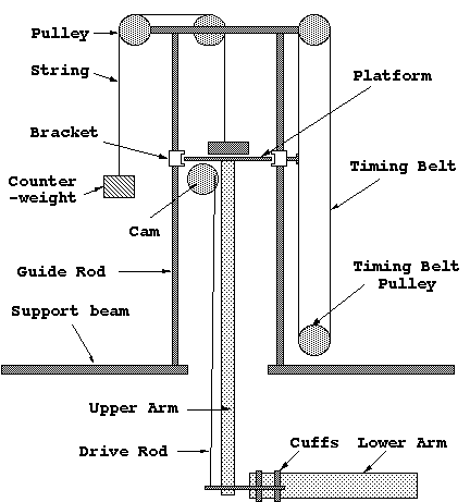 Figure 1 - Arm Design Overview
In order to discuss the various motion, an axis system has been defined as
shown in Figure 2. the z-axis is directed upwards out of the vertical section
of the arm. The x-axis is perpendicular to the z-axis in the plane defined by
the upper and lower arms, and the y-axis completes the right handed coordinate
system.
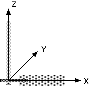 Figure 2 - Arm Axes System
The entire arm assembly is able to translate up and down on four guide rods.
This motion is powered through a timing belt drive system, were the drive
pulley is mounted to the base plate near the water and the free pulley is
mounted on the top plate. The belt is clamped to the square frame, so as the
motor at the base turns the drive pulley, the frame moves the entire arm up and
down. The linear bearings should be sufficient to carry the moment created by
driving the vertical motion from off-center, and should prevent binding as
well. In addition, the entire arm will be counterweighted to reduce the load on
the motor driving the belt. The line for the counterweight will run through two
pulleys mounted on the top plate.
Previously, the option of driving the vertical motion using a lead screw or a
rack and pinion had been discussed, and in fact, the lead screw was preferred
as recently as the Oral Design Review. However, based on the fact that it would
be very difficult (and expensive) to find a lead screw that was capable of
moving the arm with sufficient speed, the more direct approach of a timing belt
has been chosen.
To enable the rotation around the z-axis, a motor is mounted in a corner of
the square frame so that its axis is vertical. A six-inch timing belt pulley is
mounted in the center of the circular disk, and a timing belt running between
this pulley and the motor drive the rotation about the vertical axis. The Setup
is pictured in Figure 3.
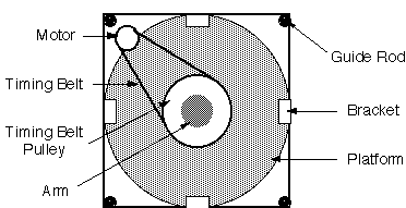 Figure 3 - Top View of Platform
During this motion using a rack and pinion system has also been considered
However the difficulties encountered in trying to locate a circular rack, and
the added requirements of alignment lead to the choice of the much simpler
timing belt.
The lower arm must be pivoted up and down, rotating about the lower joint. The
mechanism chosen to accomplish this is a push rod. A five inch diameter
circular disc is mounted on a motor on the underside of the circular platform,
and one end of the push rod is pinned to one edge. The other end is pinned to
the far side of the aluminum part of the lower arm, so as the upper disc turns,
the push rod moves up and down, and the aluminum bars act as a lever, causing
the lower arm to pivot around the y-axis.
Originally, the possibility of using a gear fixed to the lower arm, and driven
using a chain from above had been discussed. But once again due to simplicity
reasons, the push rod was eventually chosen.
The decision as to what size arm to use was a fairly arbitrary one. Ideally the
lower arm section should have dimensions similar to those of an entire human
arm while in a space suit. The original plan called for a lower arm diameter of
six inches, but the drag that an arm this size produced was determined to be
too large, and the required torques would necessitate heavy motors that would
be difficult to obtain. (see Appendix 2) For this reason, the diameter of the
arm was reduced to four inches, and its length was reduced from 40 inches to 30
inches. Originally, the upper arm was to have the same diameter as the lower
arm as it was to house the chain drive mentioned above, but as the design
progressed, it was determined that this would be a waste of material, and an
upper arm diameter of two inches was chosen. The length of the support rods and
of the upper arm were determined based solely on the depth of the tank. The
depth of the tank is approximately four and a half feet, so there is
approximately three and a half feet of space for vertical translation. With
motors and other protrusions occupying six inches of space, the height of the
guide rods becomes four feet. A height of four and a half feet for the upper
arm was then chosen as it will allow the lower arm to be six inches from the
bottom of the tank when at the bottom of the guide rods.
The foils will be constructed of foam, which will be cut to the correct shape
using the foam cutter. Once in the correct shape, weights will be added in the
form of metal strips to make the overall structure neutrally-buoyant. It will
then be coated with a layer of fiberglass to make the foil waterproof. The two
variables in choosing the foil shape are the overall geometry, and the length.
NACA 4-digit standard airfoils have been chosen because their shapes are easily
calculated. The lengths were chosen to provide a range in foil shape, but
without being too long to be used on an actual human arm during simulations. A
maximum length of 19 inches has been prescribed. The determination of this
maximum length is rather subjective, and more detailed studies will need to be
done in the future to validate this as an acceptable length. Because
symmetrical NACA 4-digit airfoils are being used, the only parameter remaining
to be determined is the thickness ratio. This is the maximum thickness of the
airfoil divided by the chord length, which gives you a percent of chord. The
maximum thickness is constrained by the four inch diameter arm on which the
foils are placed to be no less than five inches. Based on this maximum
thickness, the thickness ratio for a chord length of 18.5 inches would be
approximately 27% and that for a chord length of 12.5 inches would be 40%. The
NACA four digit designations for the airfoils then follow as NACA 0027 and NACA
0040. Figure 4 shows the basic concept.
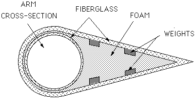 Figure 4 - Foil Cross-Section
The ribbon fairing is an addition to the experiment that is basically a number
of ribbons that are free to stream off the trailing edge of the cylinder. In
theory, these ribbons are supposed to prevent the initiation of vortex
shedding, where vortices come off the trailing edge and detach either upwards
or downwards, in an alternating fashion. The ribbon fairing will be basically
two loops around the cylinder connected by a small lexan plate, to which the
ribbons are attached. It is pictured in Figure 5.
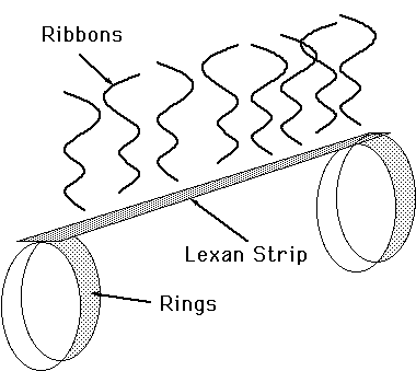 Figure 5 - Ribbon Fairing Concept
The only instrumentation that is actually on the arm itself is the strain
gauges. These will be placed on the aluminum bars in the lower part of the arm,
where they will measure the actual drag torques and forces while the arm is in
motion. The diagram detailing their placement is pictured in Figure 6. See
Appendix 3 for information regarding the expected values of the strains when
testing the cylinder.
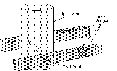 Figure 6 - Strain Gauge Placement
The minimum torque for the motors that must be used in the experiment can be
found in Appendix 2. Originally it had been hoped that stepper motors would be
able to move and control the arm. Unfortunately, stepper motors do not deliver
enough torque, and so a different control strategy is required. The motors will
be controlled using timing circuits and limit switches. The motor that controls
the pivoting of the lower arm can be run continuously to give a continuous back
and forth motion. The motor that controls rotation can be run for multiple
revolutions to give an extended experiment time. The only motor that really
needs a control system is the motor that provides the translation. Limit
switches will be used to reverse the polarity of the motor and allow for
continuous vertical translation. If a more complex maneuver is desired, then
the timing mechanisms can be used to independently control each motor through
its sequence of motions.
A spare PC with an analog to digital converter board inside will serve as the
primary means of data collection. For some experiments, the motion will be
recorded using a video recorder, which can provide another source of position
information.
The current test matrix is pictured below in Figure 7.
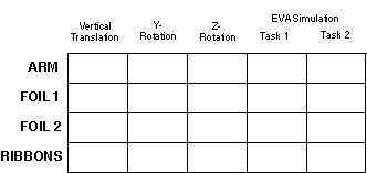 Figure 7 - Test Matrix
* Removed Low Drag Coatings from the primary objective.
* Added Ribbon
Fairing.
* Measuring Torques and force directly using strain gauges.
*
Using the Aero/Astro tank in Building 41.

Note: end of "body"; "end" starts here

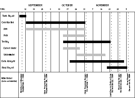 Figure 8 - Fall Schedule
   QUANTITY	ITEM				STATUS

	9'	4" Diameter PVC Pipe		Order
	8	Endcaps				Order
	4	Timing Belt Pulleys		Available
	1	8' Timing Belt			Available
	1	2' Timing Belt			Available
	2	Regular Pulleys			Available
	6'	String				Available
	1	2" Diameter Tube, 54" long	Available or Order
	4	Support Rods, 48" long		Available or Order
	4	Linear Bearings			Available
	2	Aluminum Bars (10"x.2"x.4")	Available
	4	6" Aluminum Strips (cuffs)	Available
	1	14" Diameter Disk, 3/8" Lexan	Order
	1	14"x14" Lexan Plate		Order
	4	14" Aluminum Bars		Available
	1	54" Drive Rod			Available
	1	5" Diameter Lexan Cam		Available
	5	Aluminum Blocks			Available
	3	20 in-lb Motors			Order
	3	Timing/Control Mechanisms	Available
		Strain Gauges			Available
	Miscellaneous:
	Foam, Fiberglass, Scrap Wood/Aluminum	Available
During translation, the force per unit length is constant across the entire
lower arm.

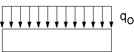 Figure A2.1
Where V is velocity, CD the coefficient of drag, and R the
radius of the cylinder. The total drag on the cylinder is then

The Moment created at the root is:

During any kind of rotation, the load on the arm is going to vary parabolically
with distance,

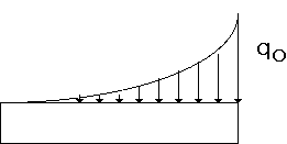 Figure A2.2
To find the equipollent force and moment, we integrate the above over the
length:

To find where the equipollent force acts, we find the x where

So the net Moment at the root is

In the current design, R = 2 in, l = 30 in,
 = 30 deg/sec, V = 1 ft/sec.
For the rotational cases,

For the translational case,

Required Torque for pitch motor (push rod with cam)
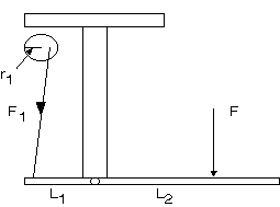 Figure A2.3
Figure A2.3 shows the mechanical linkage for this motion. The moment that needs
to be overcome is
 .The
force in the push rod will create this using l2 as the moment arm.
Therefore,

Required Torque for rotation motor (small belt drive)
 Figure A2.4
Figure A2.4 shows the linkage for this motion. Here the torque depends simply
on the ratio of the sizes of the pulleys.

Required Torque for translation motor (large belt drive)
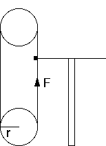 Figure A2.5
Figure A2.5 shows the setup of this motion.

In the old design, R = 3 in, l = 40 in,  =
30 deg/sec, V = 1 ft/sec.
For the rotational cases,

For the translational case,

In the old design, the following would be the required motor torques:

In choosing the size of the two Aluminum bars that support the lower arm
section, the amount that they would strain under the expected loads needed to
be taken into account. A thickness of 0.2 in and a height of 0.4 in has been
chosen. This will provide strains in the range of 0-150 
 , which
should be detectable using readily available strain gauges. In calculating the
strain, the following steps were taken:
* t, the thickness, and h, the
height, are the inputs (in inches)
* The Area Moment of Inertia, I, was
calculated for both deflection around z and deflection around y:

* Next, the stresses were determined using
 ,
so
,
so

* The various strains were calculated using
 ,
where E for Aluminum is approximately 10 msi. Since all the strains are
occurring in roughly the same place, they are added to get an idea of what the
total strain to the structure will be.
The results are tabulated in Figure A3.1.
 Figure A3.1 - Summary of Strain Calculations


Figure 1 - Arm Design Overview
Figure 2 - Arm Axes System
Figure 3 - Top View of Platform
Figure 4 - Foil Cross-Section
Figure 5 - Ribbon Fairing Concept
Figure 6 - Strain Gauge Placement
Figure 7 - Test Matrix


Figure 8 - Fall Schedule
Figure A2.1
Figure A2.2
 = 30 deg/sec, V = 1 ft/sec.
Figure A2.3
 .The
force in the push rod will create this using l2 as the moment arm.
Therefore,
.The
force in the push rod will create this using l2 as the moment arm.
Therefore,Figure A2.4
Figure A2.5
 =
30 deg/sec, V = 1 ft/sec.
 , which
should be detectable using readily available strain gauges. In calculating the
strain, the following steps were taken:
 ,
so
,
so ,
where E for Aluminum is approximately 10 msi. Since all the strains are
occurring in roughly the same place, they are added to get an idea of what the
total strain to the structure will be.
,
where E for Aluminum is approximately 10 msi. Since all the strains are
occurring in roughly the same place, they are added to get an idea of what the
total strain to the structure will be.Figure A3.1 - Summary of Strain Calculations