1.0 Introduction 2
2.0 Approach 3
3.0 Experimental Configuration 4
3.1 Nozzle and Straight Section Design 4
3.2 Diffuser Design 5
3.3 Bump Design 5
3.4 Actuator Design 5
3.5 Velocity and Frequency Design 6
4.0 Test Matrix 6
5.0 Equipment and Materials 7
6.0 Data Collection and Analysis 7
7.0 Procedure and Schedule 8
8.0 References 9
1. Diffuser Configuration 2
2. Effect of Bumps 2
3. Flow Regimes in Two-Dimensional Straight Walled Diffuser 3
4. Schematic of Components and Stand 4
5. Dimensions of Components 4
6. Speaker Locations 6
7. Test Matrix 6
8. Work Schedule for Spring Term and Fall Terms 8
A diffuser is used to decelerate the air flow entering an engine. The
performance of a diffuser is measured by the pressure gradient across the
diffuser and is determined by the divergence angle. The maximum divergence
angle of a diffuser is limited by flow separation. In this project, a "bump"
will be placed in the diverging wall of the diffuser where the separation of
the flow is expected to occur in the attempt to delay separation. A
disturbance created by the actuator, a loudspeaker, will impinge on the "bump"
and create a scaled-down disturbance closer in size to that of the separating
flow section along the wall of the diffuser. The experiment will determine if
this new, smaller disturbance is effective in delaying the flow separation and
thus improving diffuser performance.
Diffusers are used in engines to decelerate the entering air flow. The
amount of deceleration and hence the performance of a diffuser is primarily
dictated by the divergence angle, shown in Figure 1. For a fixed inlet width,
a larger divergence angle will result in better performance, usually defined by
a higher pressure gradient along the length of a diffuser. The divergence
angle is limited by the advent of stall, flow separation along the walls of the
diffuser. The separated region acts as a blockage and narrows the effective
width of the diffuser. As a result, stall leads to decreasing pressure
recovery and performance.
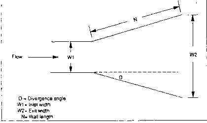 Figure 1: Diffuser Configuration
Previous research has shown improvements in diffuser performance using air
jets to impart momentum to the flow and flaps and speakers to introduce
oscillations in the flow[1-4]. The oscillations introduced in the
flow by a speaker may be improved by placing "bumps" in the diverging wall of
the diffuser. Research has shown that bumps increase the acoustic receptivity
of the boundary layer[5]. The bumps could make the boundary layer of
the diffuser more responsive to oscillations. A bump is approximately 100
microns high and 1 cm wide.
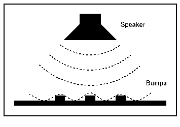 Figure 2: Effect of Bumps
The objective of this project is to determine the effectiveness of the bumps
in delaying flow separation. The bumps will be placed where the flow is
expected to begin separating. According to research, this is the area where
greatest receptivity is predicted to occur.[5] The oscillations
produced by the loudspeaker, as shown in Figure 2, will impinge on the bump and
generate scattered, scaled-down oscillations closer in size to that of the
separating flow section along the wall of the diffuser. This scaled-down
oscillations will make the separated region oscillate. Once these oscillations
reach resonance, the high amplitude of the oscillations could make the flow
reattach. The delay of flow separation may enhance diffuser performance but
may also provide structural and economic advantages by allowing larger
divergence angles. For a given flow velocity, a larger divergence angle would
result in a shorter, lighter, and hence, cheaper diffuser.
Open-loop tests will be conducted in the 1' X 1' wind tunnel at MIT. The
efficiency of the diffuser with the bumps will be tested in the region of
transitory stall. The range of diffuser divergence angles is dictated by the
ratio N/W1 of the diffuser as shown in Figure 3.
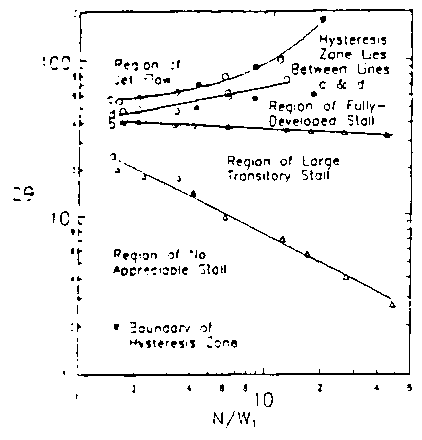 Figure 3: Flow Regimes in Two-Dimensional
Straight Walled Diffuser[3]
Since the Written Proposal, there have been several changes to the
project approach. Instead of conducting open-loop and closed-loop tests, we
will only be performing open-loop testing due to the time constraint. Instead
of developing an actively controlled diffuser, the focus will be on determining
the effectiveness of the bumps in delaying stall. We will vary the number of
these bumps and the spacing between them for three different divergence angles
 of 5, 10, and 15 degrees. In the experimental setup, we have added a
straight section between the nozzle and the diffuser to make the flow
transition smooth. Also, the speaker will be placed in two different
positions: mounted on the top wall of the diffuser and at a distance from the
diffuser exit.
The experimental configuration is composed of a nozzle, straight
section, diffuser and stand. It was designed to be used with the 1 foot by 1
foot wind tunnel. A schematic of this setup is shown in Figure 4.
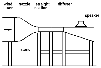 Figure 4: Schematic of Components and Stand
The purpose of using a nozzle instead of attaching a diffuser directly
to the wind tunnel is to obtain a smooth flow in the diffuser inlet. Also, the
exit of the nozzle will require a smaller diffuser than the plain exit of the
wind tunnel. A schematic of the existing nozzle is shown in Figure 5. The
inlet height and width is 1 foot to fit the wind tunnel. The exit height is 3
inches.
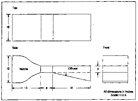 Figure 5: Dimensions of Components
After the nozzle, there will be a straight section so that the
transition of the flow from the nozzle to the diffuser is gradual. The
dimensions of this section will be a length of two nozzle exit heights, 6
inches, and a height of 3 inches.
The straight section will be connected to the diffuser. The design of
the diffuser was based on the ratio of the length of the diffuser (N) to the
width (W1) of the diffuser. For a ratio of 6, which would make the diffuser
shorter and easier to work with, N is 18 inches for a W1 of 3 inches. The
width of 3 inches was determined by the existing nozzle. A schematic of the
dimensions of the diffuser is shown in Figure 5.
The performance of the diffuser with the bumps will be tested in the region of
transitory stall. With a ratio N/W1 of 6, the range of divergence angles in
this region of transitory stall is between 10 and 30 degrees (this is
2 ), as shown in Figure 3. For this project, the divergence angle
settings for the diverging wall will be 5, 10, and 15 degrees (this is
 ). These three angles were chosen as representative of the range of
possible divergence angles
  with different degrees of flow
separation.
The bumps will be strips of tape which is currently being used in
Prof. Breuer's lab for this type of research. The height of the bump is 100
microns and the width is 1 centimeter. The height of the strips must be small
enough to prevent flow separation. The length of the bump will be the width of
the diffuser which is 1 foot. The bumps will be placed in the diverging wall
of the diffuser. The first one will be placed where the flow begins to
separate for a given frequency and the rest will be placed alternately upstream
and downstream of the first bump.
The number of the bumps as well as the spacing between the bumps will be
varied. The number of bumps placed in the diffuser diverging wall will be 1, 3
and 5 bumps. The spacing between the bumps will be the width of the tape
strip, twice the width of the tape strip and one and one half the tape strip
width (1, 2, and 1.5 cm.)
The actuator will introduce the initial disturbance in the flow and
enable the bumps. For this project a loudspeaker will be used since it can be
operated at the frequencies that will be needed to affect the boundary layer.
This frequencies range from 200 to 300 Hz. The loudspeaker will be placed in
two different positions. For half of our tests, it will be mounted flush with
the straight wall of the diffuser through a hole having the same diameter as
the speaker and protected by a wire mesh from the flow. In the other half of
our testing, the speaker will be placed a distance of two maximum exit widths
(W2) or 16 inches from the exit of the diffuser and the top wall of the
diffuser will be replaced with a new uncut wall. It may be interesting to see
if the actuator can influence the behavior of the diffuser at a distance. Both
speaker locations are shown in Figure 6.
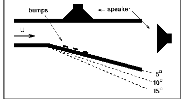 Figure 6: Speaker Locations
For this project, the wind tunnel velocity will be set at 50 m/s. The
frequency will be determined from the Strouhal number. This dimensionless
factor relates the diffuser inlet height and wind tunnel velocity to the
frequency.
As before, the test matrix, shown in Figure 7, consists of one half of
the tests conducted with the speaker mounted on the wall of the diffuser and
the other half of the tests will have the speaker at a distance two times the
exit height of the diffuser. Then each set of tests will have a different
combination of number of bumps and spacing of bumps.
The testing will be conducted in three phases. For each phase, the flow
velocity, the frequency, and the divergence angle,  , will be set.
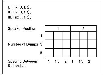 Figure 7: Test Matrix
Following is a list of the materials and equipment required and the
status of each.
Material Status
Nozzle Available
Plexi-glass On Order
(15 sq. ft. for diffuser)
Wood On Order
(50 ft., 2"X 4" for stand)
Tape Available
(bumps)
10 Pressure Taps Available
Slant Manometer Available
Hot Wire Velocity Probe Available
Pitot Tube Available
Speaker Available
Function Generator Available
Amplifier Available
Voltmeter Available
Safety Headphones Available
Miscellaneous Available
(nails, screws, sealant)
To assess the effectiveness of the bumps in diffuser performance, the
experimental data obtained in this project will be compared to the previous
research related to delaying diffuser stall and acoustic receptivity. We will
compare the coefficient of pressure, defined as the pressure rise normalized by
the dynamic pressure, and the divergence angle. The pressure will be measured
by 10 pressure taps spaced 2 in. from each other in the diverging wall. The
hot wire velocity probe will be used to determine when the flow begins to
separate in the diverging wall. Separation of the flow is characterized by the
deceleration of the flow. A pitot tube will be placed at the inlet to measure
the velocity of the incoming flow.
As shown in Figure 8, the background research and the design has been
completed. The materials are available or have been ordered. Next term, the
diffuser will be built and the test structure will be assembled. The first
part of testing will include tests to determine where the flow separates for a
given frequency and divergence angle. Then the testing will continue with the
placement of different combinations of divergence angle, speaker location,
bumps, and bump spacing. The work schedule is given in more detail in Figure 8.
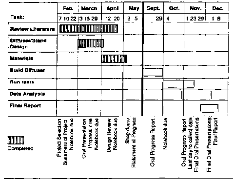 Figure 8: Work Schedule for Spring and Fall Terms
1. Chen, D., Z. Sheying, "Control of Separation in Diffusers Using
Forced Unsteadiness." Nanjing Aeronautical Institute. AIAA 89-1015, 1989.
2. Oh, David, "Active Control of Airflow Instabilities in 2-D Diffusers."
16.622 Final Report, MIT, 1990.
3. Atkins, S., "Development of an Active Control System to Suppress, Using
Forced Unsteadiness, Separation in Low-Speed Diffuser Flow." 16.622 Final
Report, MIT, 1990.
4. Kwong, A., Dowling, A.P., "Active Boundary Layer Control in Diffusers."
Cambridge University: Cambridge, UK. AIAA-93-3255.
5. Wiegel, M., Wlezien, R.W., "Acoustic Receptivity of Laminar Boundary Layers
over Wavy Walls." Illinois Institute of Technology: Chicago, IL.
AIAA-93-3280.
 Figure 1: Diffuser Configuration
Figure 1: Diffuser Configuration
Figure 2: Effect of Bumps
	Figure 3:  Flow Regimes in Two-Dimensional
	              Straight Walled Diffuser[3]
 of 5, 10, and 15 degrees. In the experimental setup, we have added a
straight section between the nozzle and the diffuser to make the flow
transition smooth. Also, the speaker will be placed in two different
positions: mounted on the top wall of the diffuser and at a distance from the
diffuser exit.
of 5, 10, and 15 degrees. In the experimental setup, we have added a
straight section between the nozzle and the diffuser to make the flow
transition smooth. Also, the speaker will be placed in two different
positions: mounted on the top wall of the diffuser and at a distance from the
diffuser exit.Figure 4: Schematic of Components and Stand
Figure 5: Dimensions of Components
 ), as shown in Figure 3. For this project, the divergence angle
settings for the diverging wall will be 5, 10, and 15 degrees (this is
 ). These three angles were chosen as representative of the range of
possible divergence angles
  with different degrees of flow
separation.
with different degrees of flow
separation.Figure 6: Speaker Locations
 , will be set.
Figure 7: Test Matrix
Figure 8: Work Schedule for Spring and Fall Terms