1.0 Introduction 2
2.0 Background and Approach 3
2.1 Background 3
2.2 Approach 4
3.0 Research Methodology 4
3.1 Design and Construction 4
3.2 Data Collection 5
3.3 Testing 5
3.4 Data Analysis 5
4.0 Work Plan 6
5.0 Budget 6
5.1 Diffuser/Active Control System Construction 6
5.2 Testing Equipment 6
6.0 Conclusion 6
1. Diffuser Configuration 2
2. Flow Regimes in Two-Dimensional Straight Walled Diffuser 3
3. Creation of Disturbances in the Flow 4
4. Schedule for Spring Term and Fall Term 1994 6
The performance of a diffuser is measured by the pressure gradient
across the diffuser and is determined by the divergence angle. The maximum
divergence angle of a diffuser is limited by flow separation. Previous
studies have suggested the advantages of an actively controlled diffuser to
postpone flow separation. In this project, a diffuser and an active control
will be designed and tested to determine the feasibility of an actively
controlled diffuser. Both, open-loop tests and closed-loop tests will be
conducted.
Diffusers are used to decelerate the air flow entering an engine. The
amount of deceleration and hence the performance of the diffuser is primarily
dictated by the divergence angle, shown in Figure 1. For a fixed inlet width,
a larger divergence angle will result in better performance, usually defined by
a higher pressure gradient along the length of a diffuser. The divergence
angle is limited by the advent of stall, flow separation along the wall of the
diffuser. The separated region acts as a blockage and narrows the effective
width of the diffuser. As a result, stall leads to decreasing pressure
recovery and performance.
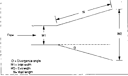 Figure 1: Diffuser Configuration
This project examines the feasibility of implementing active feedback control
to postpone the onset of stall. The feedback control will "sense" the coming
flow stall and introduce disturbances into the flow to delay separation. An
actively controlled diffuser not only will enhance the diffuser performance but
also will provide structural and economical advantages by allowing larger
divergence angles. For a given flow velocity, a larger divergence angle will
result in a shorter, lighter, and hence, cheaper diffuser.
The experiments will be conducted in the 1' X 1' wind tunnel at MIT. Both,
closed loop and open loop tests will be conducted. The efficiency of the
actively controlled diffuser will be tested in the region of transitory stall
with a range of diffuser divergence angles between 10 and 30 degrees. The
range of diffuser divergence angles is dictated by the ratio N/W1 of the
diffuser as shown in Figure 2.
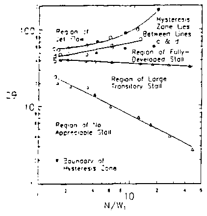 Figure 2: Flow Regimes in Two-Dimensional
Straight Walled Diffuser[3]
Previous research has implemented air jets, speakers, and flaps in
order to delay the flow separation in a diffuser. Chen and Sheying[1] demonstrated that when operating within the
region of transitory stall, the stalled region of flow could be forced to the
opposite diffuser wall by the deployment of a small flap using a closed loop
system. Oh and Miles[2] improved the
pressure recovery of a 2-D diffuser using a loudspeaker in open loop tests.
Bell and Atkins[3]found that flow separation
was reduced using airfoils to increase mixing, but their tests did not use an
active control. Most recently, Kwong and Dowling,[4] using air jets, found that the coefficient
of pressure was unaltered by the feedback.
All of the researchers who postponed the onset of stall in open loop tests
have recommended implementation of closed-loop control. However, when
closed-loop control was activated with air jets no improvement was noted.
Taking the previous research into consideration, this project will
examine the feasibility of an actively controlled diffuser. As a new approach
to the development of the control a "bump" will be placed in the diverging wall
of the diffuser before and after the region where the separation of the flow is
expected to occur. A disturbance, as shown in Figure 3, created by the
actuator when it senses the coming stall, will collide with the "bump" and
create a smaller disturbance closer in size to that of the separating flow
section along the wall of the diffuser. The experiments will determine if this
new, smaller disturbance is effective in delaying the flow separation instead
of a direct signal from the actuator.
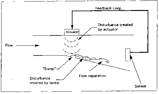 Figure 3: Creation of Disturbances in the Flow
In preparation to test the feasibility of an actively controlled
diffuser, a diffuser and active control system need to be designed and
constructed. The design of a 2-D diffuser will be based on the design of an
existing nozzle that can be attached to the wind tunnel. The purpose of using
a nozzle instead of attaching a diffuser directly to the wind tunnel is to
obtain a smooth flow in the diffuser inlet. Also, the exit of the nozzle will
require a smaller diffuser than the plain exit of the wind tunnel. This
diffuser will then resemble a potential space application. The diffuser will
have a movable wall so that the divergence angle can be varied. The flow
velocity through the wind tunnel as well as the actuation frequency will also
influence the diffuser configuration. The active control system design will
require exhaustive research. A speaker is a possible actuator alternative
since it is easier to operate than air jets and flaps. A sensor alternative is
a hot wire probe to measure the flow velocity. This sensor would give a direct
indication of when the flow begins to separate since flow separation is
characterized by a decrease in flow velocity. After the preliminary designs
are completed, the test articles will be constructed and assembled in the wind
tunnel.
Qualitative and quantitative flow data will be collected. Qualitative
observations will be made using a set of threads placed along the wall of the
diffuser. These threads will visually depict the behavior of the flow.
Quantitative flow velocities will be collected using a hot wire probe.
Pressure information can be directly extracted from the flow velocities. The
pressure drop across the diffuser can be found by subtracting the pressure at
the exit from the pressure at the inlet. Additionally, the frequency, phase,
and amplitude of the active control signal will be recorded for each divergence
angle using a data acquisition system.
The diffuser and its active control system will be tested in the 1'X1'
wind tunnel at MIT in two phases: open loop and closed loop tests. For
each phase there will be flow visualization testing as well as tests to record
the frequency, phase, and amplitude of the feedback control signal at the
different divergence angles. The diffuser divergence angle will be varied from
10 to 30 degrees so that the diffuser operates at the threshold of transitory
stall.
For both phases, there will be two stages of testing. The first stage of
testing for each phase will be used to determine how the system works and to
determine if changes need to be made. The second stage will involve finding
the divergence angle for optimal diffuser performance. Diffuser performance is
given by pressure change across the diffuser.
The data will be analyzed using MATLAB software. The data analysis
will be divided into two main categories: open-loop testing and closed-loop
testing. The open loop data represents a description of the behavior of the
diffuser and will be the reference set of data for the system. This reference
data will indicate the optimum divergence angle for a diffuser performance with
no feedback. The closed-loop data will indicate the highest divergence angle
for a diffuser before the onset of stall using feedback. A comparison of the
closed-loop data and the open-loop data will indicate the effectiveness of the
feedback.
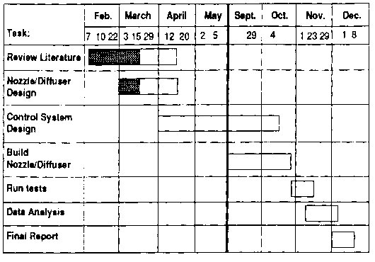 Figure 4: Schedule for Spring Term and Fall Term 1994
The diffuser will be constructed from plexiglass. The active control
system will consist of an actuator and a sensor. The actuator will be
determined by the design of the diffuser which will define the required
frequencies. The sensor, a hot wire probe, will be provided by the project
advisors. The budget for these materials should not exceed $200.
The active control system will require a data acquisition system.
Also, the testing will require the use of the 1' X 1' wind tunnel test
facility at MIT.
Previous studies have suggested the advantages of an actively
controlled diffuser, but no one has successfully implemented such a control in
a diffuser. This project will determine the feasibility of the application of
active feedback control to postpone the onset of stall in a diffuser. If the
flow separation is successfully delayed, diffusers will be able to operate at
a higher divergence angle and, hence, at an enhanced performance.
 Figure 1: Diffuser Configuration
Figure 1: Diffuser Configuration
	Figure 2:  Flow Regimes in Two-Dimensional
	              Straight Walled Diffuser[3]
Figure 3: Creation of Disturbances in the Flow
Figure 4: Schedule for Spring Term and Fall Term 1994