 |
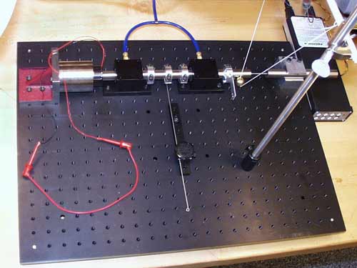
Figure 1: The second-order system
with voice coil, air bearings, adjustable spring,
shaft mass and LVDT sensor |
In this lab, the dynamics of a second-order
system composed of a spring, mass and damper are examined. As shown in
figure 1, the system consists of a cilindrical shaft riding on air bearings.
A voice coil is attached at the left side to add variable damping. The
voice coil armature is wound on an aluminum cilinder. If the coil is open-circuited,
some damping is still present due to eddy currents in the aluminum. If
we short-circuit the voice coil the damping is increased significantly,
because of resistive losses in the wire. In the middle between the two
air bearings, an adjustable spring is attached to the shaft. By decreasing
the length of the spring, the natural frequency of the system is increased
and the damping ratio is decreased. By adjusting the length of the spring,
one can demonstrate overdamped, critically damped and underdamped behavior.
A pulse can be applied to the system by allowing a small brass ball hanging
on a piece of string to impact the plate attached to the shaft at the right.
To measure the motion, an LVDT (Linear Variable Differential Transducer)
is fixed on the right side of the shaft. See Prelab3.pdf
page 5 for an explanaition of LVDT operation. The signal passes through
a signal conditioner and is made visible on an oscilloscope (figure 5 and
6). Figure 2 shows the drawing of this system and figure 3 shows the idealization
of its dynamics.
Note the schematic detail in figure
2 that shows the off-center attachment of the spring to the collar on the
shaft. The reason for this is to allow for axial displacements of the end
of the spring by free rotation of the shaft. If the spring is bend, it
shortens a distance d, as shown in figure 2 on the bottom right. If the
spring was not attached this way, the actual stiffness would be much larger.
More importantly, the linearity of the stiffness would be much less because
of the unwanted axial pulling force on the spring rod. |