The Challenge: Design a visually streamlined and tightly integrated alarm clock which overcomes the user interface difficulties present in most modern digital alarm clocks.
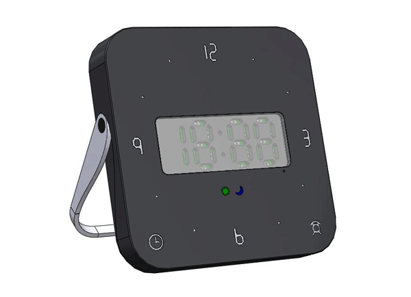
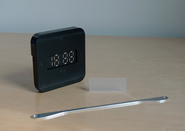
Technical Approach: Twelve capacitive touch sensors are located around the face of the clock in the same positions as the hours on a traditional analog clock. The alarm can be set by touching the desired hour and five-minute positions. The key realization which enables this design is that most people do not require single-minute precision in setting their wake-up time. By relaxing the resolution to five minutes, the number of buttons required for direct entry becomes feasible and the alarm can be set with only three button presses. A functional prototype was constructed in 2005, although the final embodiment still remains unfinished (the state of which is documented photographically below).
Selected Design Features: Capacitive touch sensors were selected because they prevent the visual clutter inherent in placing so many buttons in such close proximity. An additional benefit is a reduced component count, as the sensors can be built as traces on the clock's PCB. Every aspect of the enclosure was designed on the golden ratio, including the LED display font. The pivoting aluminum legs are limited in travel by features in the delrin enclosure, and magnetic detents are provided for a proper feel. A light sensor adjusts the display intensity based on the ambient lighting. Because no visual feedback is required to accurately set the alarm, this design could be readily adapted with braille buttons for use by the blind.
 |
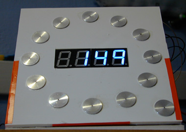 |
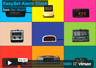
| Concept video (click to view). | The initial working prototype. Aluminum discs serve as capacitive touch sensors. These will be integrated onto the PCB in the next version. |
 |
 |
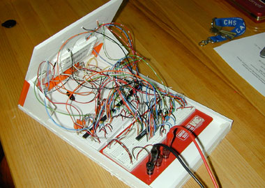
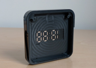
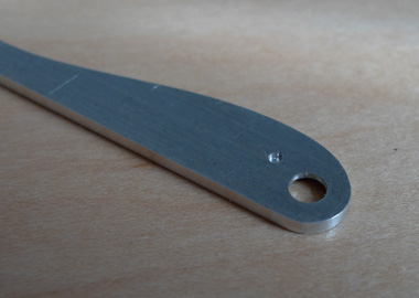
| A microcontroller and three capacitive touch ICs are what make the prototype tick. | Machined components of the new integrated design. |
 |
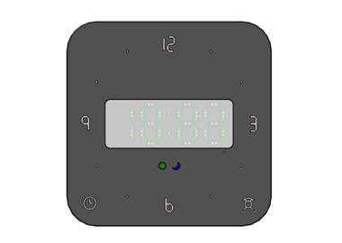 |
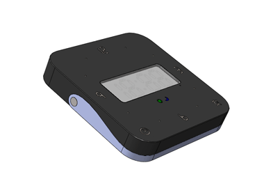
| The housing is machined out of plate delrin. | The silkscreened numbers share a common font with the custom LED display - all designed on the golden section. |
 |
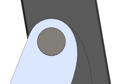 |
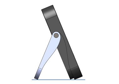
| The legs pivot to support the clock on a table. Three lines of contact are made with the table when the clock is fully reclined. | The maximum rotation of the legs is limited by the geometry of the pocket in which they sit. |
 |
 |
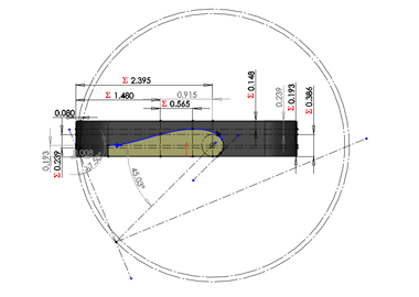
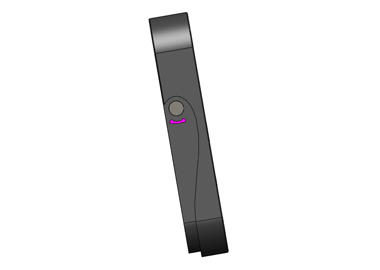
| The geometry of the legs are designed using a golden ratio system. This method was chosen to mimic the template on which our bodies are proportioned. | The legs fold into the body for convenient travel storage. |
 |
 |
| Magnetic detents are located at both extremes of the legs' travel to provide an intentional feel, and also serve to keep the legs in position during placement and storage. | Each leg has a recess for a 1/16" magnet, and a reservoir for excess glue to escape. |
 |
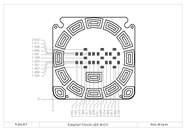 |
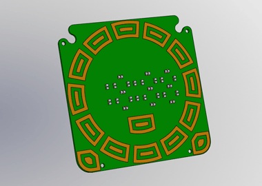
| Capacitive touch sensors are built as traces on the PCB. These and LED placement were designed in the context of the solid model. | A Mechanical Control Outline (MCO) was used to transfer information from the mechanical CAD package to the electrical CAD package. |
 |
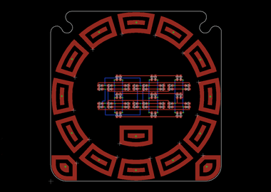 |
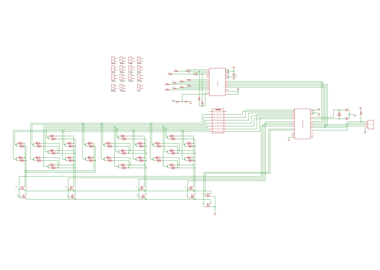
| The clock's schematic, combined with the MCOs, was used to generate a board layout. | The PCB layout remains unfinished, and is one of the last remaining milestones in this project's path towards completion. |