The Challenge: Design a machine tool as a function, where the inputs are the desired mechanical characteristics and the output is a complete design including engineering drawings and a valid bill of materials. The goal is to separate design intent from particular dimensions in a way which is reusable by others.
Technical Approach: A reference design was created and 3D modeled using SolidWorks, along with a corresponding set of engineering calculations predicting properties such table stiffness based on component sizing. These equations were then inverted to calculate the smallest components necessary to achieve stiffness goals based on the desired lengths of travel. Unfortunately, most components - such as bushings and precision shafting - are only available in discrete sizes such as 1/4", 3/8", etc. All available sizes of key components and their matching part numbers and prices (as stocked by McMaster-Carr, a leading mechanical supplier) are compiled into Excel tables. The closest sized components which satisfy the specified design requirements are automatically looked up and compiled into a bill of materials. The dimensions of these elements are linked to the SolidWorks model, causing it to update as requirements are changed in the Excel workbook. All engineering drawings based on the model are also automatically updated to provide new prints for machining.
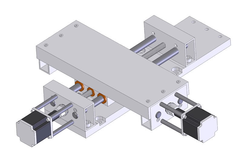
Selected Design Features: Extruded aluminum profile was used wherever possible as structural elements to provide maximum dimensional flexibility and easy fabrication. While only three degrees of freedom are user-specified (X travel, Y travel, and table stiffness), calculations were performed to inform the design regarding torsional stiffness of the motor mounts, flexural rigidity of the shaft end blocks, necessary leadscrew preload, and a host of other details.
 |
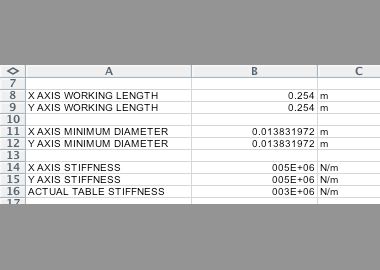 |
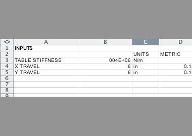
| Three inputs are specified by the user: X travel, Y travel, and table stiffness. | Minimum necessary component sizes are calculated based on specified requirements. |
 |
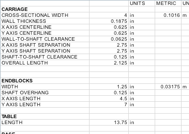 |
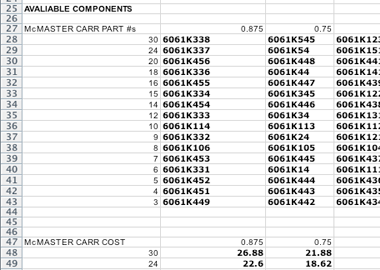
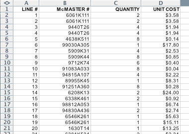
| Avaliable component sizes, along with their part numbers and prices, are organized in tables. From these tables optimal components are automatically chosen. | Dimensions of structural components and machined features (such as holes) are calculated to accomodate chosen components. |
 |
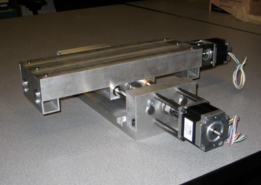 |
| A complete bill of materials satisfying the design requirements is compiled. | Aluminum extrusion is used wherever possible. |
 |
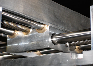 |
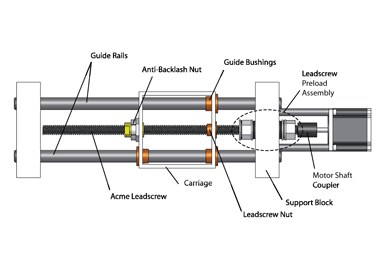
| An overview of the mechanical design of each axis. | The carriage is made of 4" square extruded aluminum tube. |
 |
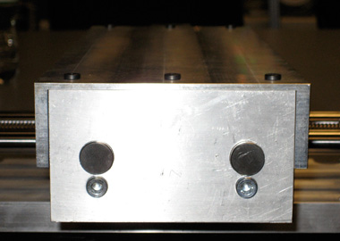 |
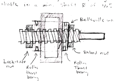
| A preload assembly bears the thrust loads generated by the leadscrew. | Threaded tapered plugs deflect material against the shaft ends, pinning them in place. |
 |
 |
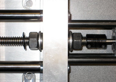
| Steel tubing mounts the motor to the end blocks. Bolt torques were estimated to give the necessary degree of torsional rigidity. | Download the design sketches (PDF) here. |
 |
|
| Download my senior thesis (pdf) here. |