How to Use the Membrane Theory to Analyze Masonry Domes Graphically
This tutorial explains how to use the online applet to analyze a masonry dome based on the method of William S. Wolfe as described in Graphical Analysis: A textbook on graphic statics (Wolfe 1921). Wolfe's method treats the dome as a membrane with zero thickness whose line of thrust, or force line, follows the median radius of the dome. For a more detailed background on this graphical analysis method, see the Methodology page.
Overview
This java applet was developed using Cabri Geometry II software by Texas Instruments. To learn more about Cabri, visit www.cabri.com.
Two key rules for using this applet follow:
1) "Ctrl" key + mouse drag will shift the viewing window.
2) In general, bright blue open-circle points are parameters that the user can control.
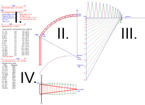
This tutorial is divided into four parts as shown:
I. User-Defined Parameters
II. Representative Dome Section
III. Force Polygon
IV. Representative Lune in Plan.
I. User-Defined Parameters
Four sliding scales are located on the left of the screen. Use these scales to define the structure's geometry and the user interface. The minimum and maximum of these values are shown and may not be modified.
Five geometric parameters in blue text
located below the first two sliders require user definition.
The applet automatically calculates the following parameters using the dome's geometry: the mean radius, thickness-to-radius (t/R) ratio, and the arc length of one voussoir (u).
II. Representative Dome Section
The dome
section is evenly divided into 16 voussoirs:
1. The u value represents the arc length of one voussoir along the mean radius and is constant for all voussoirs.
2. The w values represents the mean width of each voussoir in plan, and increases from crown to base.
The median radius is shown in alternating purple and green segments.
To include surcharge on
specified regions of the dome, move the bright blue points, some labeled with
numbers, at the center of gravity of the appropriate voussoir. Note
that this analysis assumes axis-symmetrical loading. Surcharge located at
one location on this representative lune will be assumed to occur in a ring
around the dome.
Zero hoop point: Move the point "zero hoop" to the intersection of the masonry vector and median radius. This will determine the angle at where zero hoop forces occur.
Masonry point: Move the point "masonry" along the centerline until the masonry vector intersects the median radius at the number determined by the force polygon.
Move section: Move the point "move section" to shift the dome section around the screen.
Bottom of wall: Move the blue point "bottom of wall" to elongate the wall section, which acts only to enhance the perspective of the dome section.
III. Force Polygon
The
force polygon is a graphical representation of the internal and external forces
of the structure. Details on interpreting the force polygon are included
in the Methodology section.
The vertical line with the red numbered points represent the loads on the dome for each voussoir.
The diagonal segments intersecting the vertical line at the red points and the horizontal ray of the force polygon represent the internal meridional forces.
The triangular polygons along the horizontal ray numbered in pink and green values represent the internal hoop forces.
fPoly: Move the point "fPoly" to move the force polygon around the viewing screen.
Masonry: If the dome to be analyzed is masonry, that is, the structure has little capacity to resist tensile forces, then slide the point "masonry" along the horizontal line until it intersects the location of outermost diagonal line (where the hoop force polygons transition from above to below the dark blue horizontal ray).
Note the number of the last triangle hoop force polygon above the horizontal ray.
On the representative dome section, slide the point "masonry" up the dome centerline until the pink masonry vector intersects the median dome radius at the center of gravity point with the same number from Step 1 above.
This is the modified line of thrust for a masonry structure. Note its deviation from the median radius.
Move the "zero hoop" point along the median radius to this point of intersection.
IV. Representative Lune in Plan
The Average Resultant Forces (kN/m) are provided on the left hand side of the screen for each voussoir i.
1. Hoop values: to find the total hoop force of a voussoir, multiply this value by u, the arc length of one voussoir.
Note that hoop forces are maximum compression at the crown of the dome, decrease to near zero, and then increase in tension. This corresponds with the dip in the forces shown on the plan view of the lune from the center to perimeter.
T | C divider: This vertical divider should be located approximately where the hoop forces become zero. To the left of the divider, hoop forces are in tension. For the case of masonry of masonry structures, hoop forces are zero to the left of this line. To the right of the divider, hoop forces are in compression.
2. Meridional values: to find the total meridional force of a voussoir, multiply this value by wi, the mean width of a voussoir.
Meridional force resultants listed are the values occurring through the center of gravity of the voussoir. From the force polygon, the meridional force resultant of voussoir i is given by the average length of meridional force segments which define the voussoir top and bottom edges, or (mi + mi-1) / 2.
Meridional forces are always compressive and increase from the dome's crown to base.
Representative Lune in Plan
Theta: Move point "theta" to define the number of individual lunes into which the dome is divided.
Move lune plan: Slide this point along the dome centerline to move the lune plan in the viewing window.
Return to applet.
Go to Methodology.
Return to Analysis of Masonry Domes HomePage.