This rocket was designed specifically for obtaining my NAR level 1 HPR certification. In this regard it worked perfectly! I obtained my NAR L1 cert on my first try in April of 2002. It was my first scratch-built rocket and my first time using RMS hardware. The name came as a result of the interest shown by fellow dorks at the MIT hobby shop as I was building the rocket.
Construction
Motor Assembley The lower portion of the rocket is the most complex internally, and was the most time consuming portion to build. The first step was to get the alignment holes drilled in the four centering rings and the upper bulkhead. I did this by clamping them together and drilling the entire sandwich as one piece. One small mistake here, I neglected to also dril the centering ring for the recovery assembley, which needs to align with the tube holes in the motor assembley.
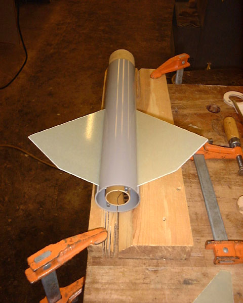
This proved difficult for a couple reasons. First, I forgot to mark the fin positions on the MMT before epoxying all of this stuff to it. Second, I accidentally applied a lower fillet to the third centering ring, which meant my fins could not rest flush up against the ring. The first problem was easy to solve. I took a hex collet and stuck a spare piece of 29mm MMT in it. By placing a pen on a block approximately half the height of the tube, i could run a line along the tube then roll the collet over two sides and draw again. In this manner, I was able to divide the circumference of the tube into thirds rather easily. The spare tube was then taped onto the end of the actual MMT and the lines were extended. The second problem was basically unsolvable at this point, so I just left a 1 mm gap between the centering ring and the top of the fins, which I would later fill with a big epoxy fillet.
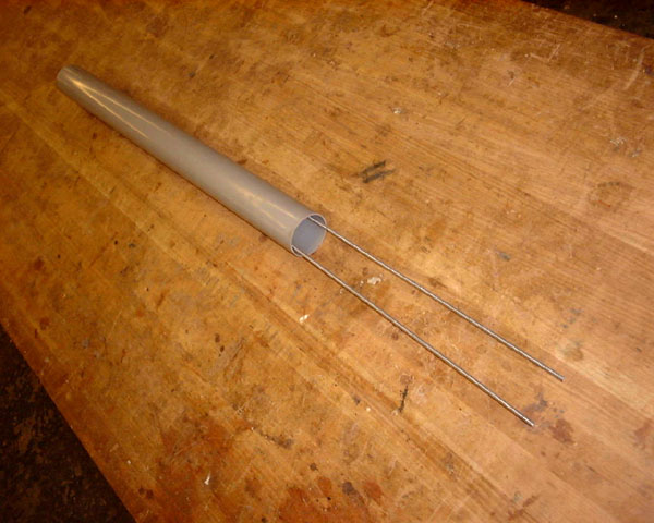
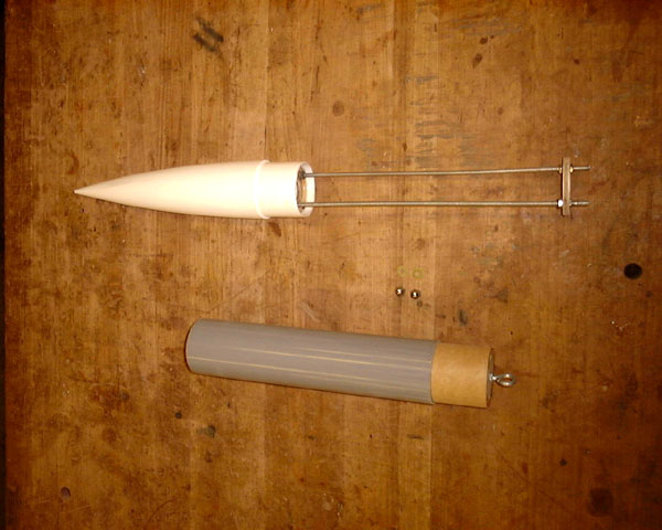
Recovery Assembley This is the most simple component of the rocket, consisting of just one piece of airframe, one centering ring, and a couple long pieces of allthread.
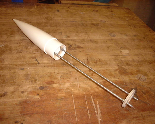
Payload Assembley
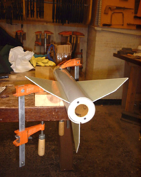
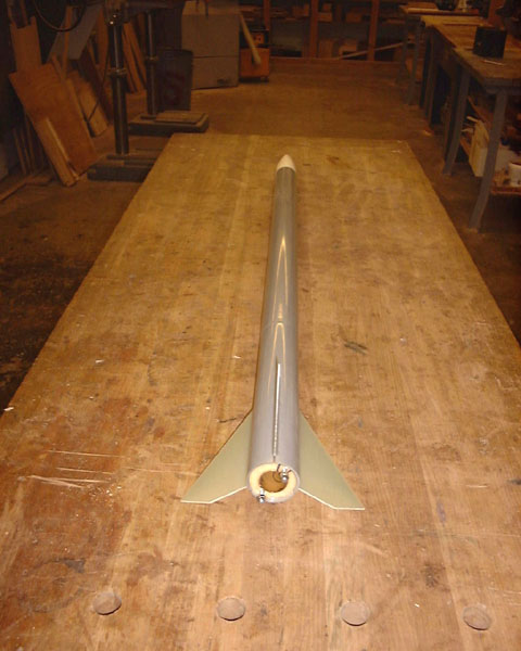
Below you can see the four main airframe components and the fully assembled rocket. 


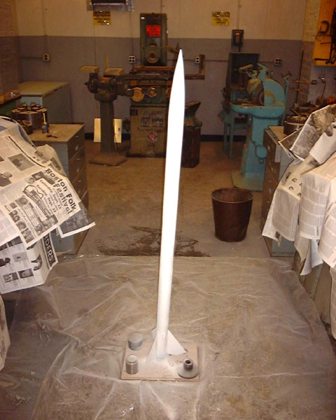
Finishing
DesignI approached the design of this rocket from the motor out. At $50, The RMS hardware represents the most expensive piece of the rocket (except, perhaps, the payload). For this reason, I wanted to be able to use the same RMS hardware for G motor test flights and for my H motor certification flight. This means using the RMS-29/180 - the only hardware that supports both G and H reloads. This gave me access to the G75J for testing and the H128W or H238T for certification.While the choice of motor hardware was financially motivated, I wanted to keep my options open for upgrades. The motor mount tube was made long enough to handle any Aerotech 29mm RMS hardware, the longest of which is 33.27cm (13.10") long. With the motor mount tube size set at 2.9x34.3cm (1.14x13.50"), I proceeded to fill the rest of the rocket design in around it. The next important decision was recovery method. I choose to design for single-stage recovery using the motor ejection charge and a piston system. This required having the recovery portion of the airframe located immediately forward of the motor. I'm considering using a steel mesh ejection baffle inside the motor assembley to alleviate the need for the piston, but I can't decide on this point. I also wanted to incorporate an avionics payload bay. This was attached to the nosecone and located just forward of the recovery tube. The airframe separation at ejection would therefore occur between the recovery and payload assemblies. The airframe has four basic sections - the motor assembly, the recovery assembly, the payload assembly, and the nosecone. I decided to permanently attach the nosecone to the forward end of the payload assembly. However, permanently attaching the recovery assembly to the motor assembly introduced some problems. The first was that it would be difficult to attach the recovery bridle to the aft end of the recovery assembly, especially if the airframe diameter was small. The second was that the open end of the airframe was subject to zippering damage during recovery, and it would be unwise to have this permanently attached to the most complex and difficult to rebuild portion of the rocket. My solution was to have a simple recovery assembly that could be detached from the motor assembly for maintenance but was securely attached during flight. The cheapest way to do this was to mount a pair of thin threaded rods to the inside edge of the recovery tube that would stick down through the entire motor assembly and out the aft end of the rocket. Here they could be bolted down with wingnuts. With the wingnuts in place, the recovery tube was securely attached to the motor assembly. With the wingnuts removed, the recovery assembly slides right off, giving easy access to the bridle connection point on the motor assembly bulkhead. This also allows for easy replacement of the relatively simple recovery tube in the case of zippering. Furthermore, the ends of the threaded rod sticking through the aft end of the rocket serve as excellent motor retainer attachment points. The only technical difficulty here was attaching the threaded rod to the recovery tube in a way that still allowed the ejection gasses to pass through to the piston, and also allowed the recovery bridle to be attached to the motor assembly bulkhead. There weren't a lot of choices on the recovery tube side; there would have to be a centering ring with large inner diameter and the threaded rods would be bolted to this. The bulkhead on the motor assembly would have to have corresponding holes running through it and through each of the motor mount centering rings. The problem was getting the eye bolt and ejection gas vent holes to fit inside the hole of the centering ring. Before I could lay down a design for this, I had to finalize the airframe diameter so I knew what sort of area I had to work with. I wanted to keep the diameter to a minimum, but still leave enough room to get the threaded rods down the side of the motor assembly and also have sufficient space for the eyebolt/vent placement at the forward bulkhead. After looking at the sizes of various threaded rods, nuts, eye bolts, and washers, I decided on an airframe diameter of 5.4cm (2.1"). This gave me 1.27cm (0.5") on either side of the motor mount tube for running the threaded rods. I wanted to use a centering ring with a 3.81cm (1.5") inner diameter in the recovery tube, but this left only 0.8cm on either side for attaching the threaded rod, and this wasn't enough. So I choose the 29mm (1.1") I.D. centering ring which gave me 1.27cm for mounting the rods. However, this restricted my eye bolt and vent hole area to a measily 3.81cm circle. The eye bolt washer took up most of this space, and with the eye bolt being the principle ejection load bearing point for the motor assembly, I couldn't afford to have it attached to the bulkhead in a flimsy manner. This left only one option: separate the motor assembly forward bulkhead and the recovery tube centering ring by some reasonable amount. In this way, ejection gas could pass through reasonably placed holes in the motor assembly forward bulkhead and then up through the recovery centering ring. This wouldn't require a terrible amount of space; a couple centimeters would do. The separation was achieved by attaching standoff blocks to the forward bulkhead in between the vent holes. Still, the presence of the vent holes in the load-bearing bulkhead made me nervous, so one last modification to the forward bulkhead was necessary. In between the vent holes and orthogonal to the line connecting the alignment rods, I decided to run another pair of threaded rods down through the next two motor mount centering rings. These rods were structurally coupled to the eye bolt with a piece of 1/16" aluminum bar stock which runs along the underside of the bulkhead. For shock absorption, a rubber washer was placed inbetween the aluminum plate and the eye bolt washer. The payload assembly, by comparison, is much simpler. It consists of the nosecone, a payload bay, and a coupler for attaching to the recovery tube. In order to keep the payload section secure during flight while allowing easy field access to the payload bay, a removeable airframe sheath was designed. The aft bulkhead of the payload assembly is epoxied to the coupler and the airframe, and has a eye bolt for attachment of the recovery bridle. These pieces are attached to the rest of the payload assembly with two threaded rods that run from the aft bulkhead to a centering ring in the nosecone. With this design, a pair of wingnuts on the aft bulkhead keep the outer airframe attached to the payload bay. The threaded rods bear the load of ejection shock axially and also serve as mounting points for the payload. As with the motor assembly bulkhead, the aft payload bulkhead is fitted with a shock absorbing rubber washer and a load bearing aluminum plate. The shock absorber, in this case, is inside the payload bay and can be replaced in the future with a load cell for monitoring dynamic loads electronically. The payload bay was designed to carry a sensor suite and flight data recorder. Care had to be taken during parts selection for this rocket to use only non-magnetic metals because of the possibility of a magnetometer in the payload. The eye bolts, threaded rods, nuts, and washers are all either type 316 stainless steel, aluminum, or brass. Parts List
RMS motor hardware (29-180 to start) assorted #10-24 hex nuts assorted #10 lockwashers assorted #10-24 acorn nuts assorted 1/4-20 hex nuts 1 1/4" lock washer assorted washers | ||||||||||||||||||||||||||||||||||||||||||||||||||||||||||||||||||||||||||||||||||||||||||||||||||||||||||||||||||||||||||||||||||||||||||||||||||||||||||||||||||||||||||||||||||||||||||||||||||||||||||||||||||||||||||||||||||||||||||||||||||||||||||||||||||||||||||||||||||||||||||||||||||||||||||||||||||||||||