Actuator Design
Description
We designed two different actuators and tested their performance.
The following picture shows the Dipole-Quadrapole Actuator (left) and
the Quad-U-Core Actuator (right). They are both designed to suspend tubes
with diameters within 0.5in.

Theory
Dipole-Quadrapole Actuator
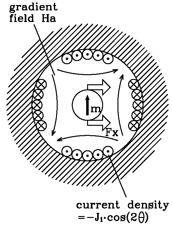
The dipole-quadrapole actuator uses a bias field to impose a dipole on the steel tube.
A quadrapole field is then added to exert a force on the tube (now a magnetic
dipole) which is linear with current and decoupled with the perpindicular
direction of motion.

Quad-U-Core Actuator
The quad-U-core actuator consists of 4 U shaped electromagnets, performing a
pull-push action on the tube in both X and Y directions. The testing result shows
this actuator has a higher power efficiency than the dipole-quadrapole actuator, and
it is easier to build. This actuator is chosen to be the 8 actuators used in the final
experiment.
Experimental Results
The following figure shows the testing result of the dipole-quadrapole
actuator. The force is
linear with input current, and decoupled in x and y directions. This
means that the control system can command a force directly by commanding
a current, rather than computing a square root as required by standard
electromagnets (which takes valuable time). Also, the fact that the
x- and y-forces are decoupled means that the control system can be much
simpler; a single-input single-output system rather than a multi-input,
multi-output system. The quad-U-core actuator also shows similar results,
and with even larger force output. The testing result is to be attached
later.
