Sensor Design
Theory
The sensor uses an alternating magnetic field to detect the position
of the tube, which passes through the center of the sensor. Three
primary poles excite a three phase field in the center of the sensor, which
changes as the position changes. The permeability of the tube is
much higher than that of air, so the magnetic field would rather travel
through the beam than through air. When the beam is off center,
more flux travels through one return pole than the other, causing a differential
voltage to occur across the output coils. An analysis of the magnetic field gives an expression for the output voltages across the secondary coils in terms of the tube position. Inverting this relationship gives the tube position in terms of the output voltages; this inversion is performed in real time by an analog circuit which outputs x- and y-position dependent voltages. These voltages are then fed into the control computer as feedback for the actuator.

Experimental Results
The sensor works well enough to levitate the tube as desired. The x- and y-output voltages are mostly linear within a 1 millimeter circle in the center of the sensor, but become more non-linear as the outer edge of the sensor is reached. The output is unique and repeatable with the tube position. With a fourth order filter on the output (to convert the sinusoidal 10kHz voltage to a constant voltage) the bandwidth is 1kHz. Sensitivity is adjustable, currently set at 2 Volts per millimeter, with a total useful range of 1cm diameter circle. At this setting, the noise is plus/minus 100 millivolts, and most of that is from the sinusoidal variation of the voltage before filtering. A higher order filter would give a sharper cutoff and reduce the noise in the output voltage.

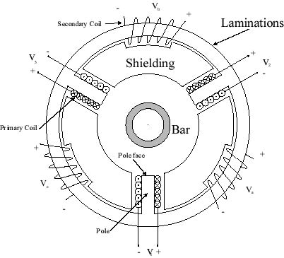
A Three-Phase Sensor, opened to show three primary coils on the poles, and three secondary coils on the ring
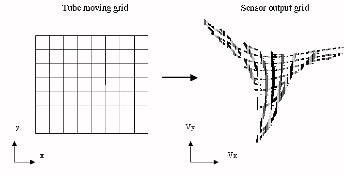
Experimental output of sensor: when the tube is moved at 1mm grid (left), the sensor output of Vx vs. Vy is shown (right)