Magnetically Suspended Artificial
Heart Pump Impeller
Professor David L. Trumper
Mr. Michael K. Liebman
Precision Motion Control
Lab
MIT Dept. of Mechanical Engineering
Sponsor: Charles E. Reed Faculty Initiatives Fund
This is a public disclosure of key ideas developed in our laboratory
for magnetically suspending a heart pump impeller. This research
was supported by the Charles E. Reed Faculty Initiatives Fund.
Introduction
Our Precision Motion Control Lab designs, builds, and controls electromagnetic
systems. We have developed magnetically levitated stages for photolithography,
an Angstrom positioning stage for scanned probe microscopy, and high force
density linear motors. Recently, we envisioned a six-degree of freedom
magnetic suspension capable of large rotations about one axis. Such
a system is similar to one of our photolithography stages which is a six-degree
of freedom magnetic suspension capable of large translations in two dimensions.
However, the application for our rotating system is to magnetically suspend
and rotate the impeller in a centrifugal artificial heart pump. This
has recently been done with many magnetic actuators and a separate motor
to spin the impeller.
Our idea is to use principles from our prior work---namely that the
motor can act as the bearings and suspend the impeller without the need
for many additional actuators---to accomplish this task more effectively.
Prior Magnetic Suspension
Our flying puck, magnetically levitated photolithography stage is an example
of a six degree of freedom stage that integrates drive force and bearings
into the same actuators. Won-jong Kim built this stage which is the
first to provide all the focusing and alignment motions required for photolithography
with one moving part. This is possible because the four linear motors
provide suspension as well as driving forces for the 5.6 kg platen supported
against gravity. This stage has a 50 mm travel in the x and y directions,
400 µm in the z direction, and can perform milliradian-scale rotations
about each of its three axes. Three laser interferometers and three
capacitance gauges are used for feedback. The stage has a position
noise of 5 nm rms in the x and y directions and can accelerate at 10 m/s2.
Rotating Suspension Idea
A variant on this stage is one in which the suspended platen would be able
to spin completely around its vertical (z) axis, and the other five degrees
of freedom would be capable of fine adjustments. This could be accomplished
by arranging the linear motors in a circular pattern. The suspension
force for the moving part is provided by the linear motors just as in the
photolithography stage. This spinning six degree of freedom stage
could have many applications such as in vacuum pumps, machine spindles,
and robotics. The application we are most excited about is as the
impeller in a centrifugal artificial heart pump. Magnetic suspensions
have recently been used in this regard due to the stringent requirements
on such a device. Our proposed suspension and drive technique is superior
to those currently used since it reduces the number of actuators required
to magnetically suspend and spin the impeller.
Conventional Heart Pumps
Each year approximately 50,000 people need heart transplants, but only
2,000 hearts are available. Artificial hearts and left-ventricular-assist
devices can sustain life until a donor heart can be found. Eventually,
it is hoped that artificial hearts might be good enough to be a permanent
solution themselves. The engineering problem of creating an artificial
heart is complex. Since the 1950's researchers have designed many
mechanical heart pumps. Reliability problems with mechanical parts,
valves, and clotting of blood have hampered these efforts. Many of
these machines were also large and cumbersome whereas we would like to
have a totally implantable design. In the last fifteen years the
biomedical community has focused mostly on rotating pump designs since
they are compact and avoid stagnation and clot formation in the blood.
Mechanical ball bearings for the rotating pump have led to clotting and
cell death, and studies show that these devices have lifetimes of only
months. Lately, magnetic bearings have been used to completely suspend
the pump's rotor in the heart pump. This solution allows large clearance
passages for the blood flow and eliminates mechanical contact and wear.
Others have designed magnetic suspensions that use a brushless motor
to spin the impeller and many electromagnets to regulate the other five
degrees of freedom. Although all three axes and three rotations are
controlled magnetically, the motoring mechanism rotating the impeller is
totally separate from the bearing mechanisms used to control the three
translations, and two other rotations.
Integrated Drive & Bearings
Our design unifies the bearings and the motor. Our motor spins the
impeller and also can regulate the other five degrees of freedom.
This results in a simpler, more compact design. Since each segment
of the motor can provide drive and suspension forces, it is easier to design
for redundancy and robustness which are essential in this application.
Figure 1 shows a possible layout for our integrated motors. We
show six motors, but only three are required to generate all required motions.
The impeller has a single circular magnet array on one side which faces
a set of stators in the heart pump housing. Each stator can generate
vertical suspension force and horizontal drive forces as shown in
Figure 2. Differential operation of the motors allows control of all six
degrees of freedom.
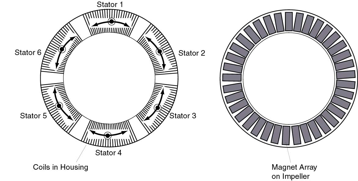
Figure 1: We show the actuators which suspend and spin the impeller.
The impeller has a single circular magnet array on one side which faces
a set of stators in the heart pump housing. Only three stators are
needed to control all six degrees of freedom including full rotations about
an axis out of the paper. We show six stators in this design so three
of them are redundant.
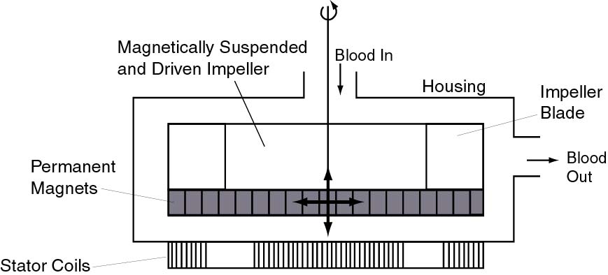
Figure 2: A cross sectional view of the impeller is shown.
Each stator can generate vertical suspension and horizontal drive forces.
Differential operation of the motors allows control of all six degrees
of freedom.
Figure 3 shows examples of how the same actuators can drive the impeller
and act as bearings. In Figure 3 (A), we see that we can generate
torque to spin the impeller for its normal operation. This configuration
of forces is equivalent to the rotary motor in conventional designs which
separate the motor and bearings into different actuators. In Figure
3 (B), we show a fine translation adjustment using just two of our actuators.
These are the same actuators that spin the impeller, but now they are acting
as bearings. The other four degrees of freedom can be generated in
a similar fashion; three of them require the use of the vertical forces
shown in Figure 2.
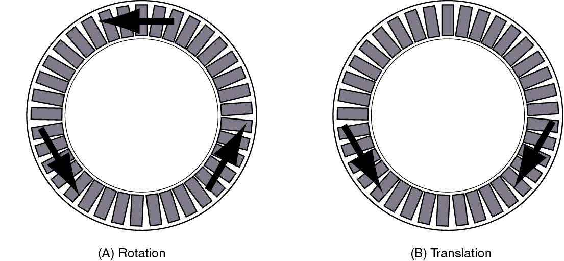
Figure 3: We show two examples of how the forces generated by
the actuators can be combined to produce rotations and translations.
We use only three actuators in these examples. In (A) we show the
forces producing the normal rotation of the impeller. In (B) we show
a fine translation adjustment.
The advantages of our design are:
-
Improved magnetic actuator and suspension design over existing designs
comprising a multitude of actuators. The actuators can provide both suspension
and drive forces to simplify the magnetic suspension.
-
Compact and integrated control, sensing, and power electronics so that
the system will be implantable.
-
Redundant and robust actuators and sensors so that the pump will continue
to work at some level in case of partial actuator or sensor failure.
-
Neutrally buoyant impeller to resist disturbance forces which will be encountered
as the heart pump is accelerated when its host person moves around.
-
Low power consumption so that recharging is required less frequently.
-
Self-sensing motor operation by using the back EMF to get position and
allow for sensorless commutation.