Dr. Thomas E.
von Wiegand
&
Andrew Brooks
Massachusetts Institute of Technology,
Research Laboratory of Electronics
Fifty Vassar St. 36-755
Cambridge, MA
tew@mit.edu
zoz@mit.edu
FootStepper: an effort-based locomotion interface
AbstractA "footstepping" effort-based locomotion interface is described. Built around an inexpensive and readily-available exercise machine, it provides an effective interface to walk-through VEs. KeywordsEffort-based locomotion, locomotion interface, virtual walk-through. 1 IntroductionThe FootStepper was created to solve a practical need for a method of moving through a large-scale virtual environment in a more realistic manner than typical hand control or gesture based interfaces allow. It is a general problem in interface design that certain modalities become "overloaded" with many functions, requiring the user to keep track of functional modes or complicated codings to achieve actions that in the real world might require little thought. In addition to this problem, there is a tendency to design controls using the prevailing interface hardware even when this hardware (e.g. a keyboard or joystick) bears only an abstract correspondence to the desired action. These tendencies are understandable given the ubiquity of keyboards and joysticks, and the ease of integrating their output into a software system, but there are clear benefits to expanding the repertoire of interface devices to more closely match the capabilities of the human body. In the present case, it is fairly obvious that, for most people, the preferred mode of moving about a large-scale (building sized) space is simple walking from place to place. A locomotion interface for a VE walkthrough should take advantage of this intuitive mode of action. There has been a great deal of work performed on locomotion interfaces appropriate to various scales of VE and tuned to different needs, including work performed at Sarcos, MERL, Virtual Space, and elsewhere, which has been summarized in the literature. Two significant interfaces worth noting are bicycle-based, for use in outdoor, very large scale worlds: Ben Brown's Tektrix bike built for Georgia Tech's virtual recreation of the Atlanta Bicycle Road Race of the 1996 Olympics, and Mike Benjamin & Thatcher Ulrich's VR Bike input device for MERL Diamond Park. These interfaces are noteworthy because they show what can be accomplished by combining commercially available parts (like bicycles) with clever motorized attachments for simulating the forces that normally occur when moving through the world. In the area of walking interfaces, the seminal work on the "Virtual Perambulator" (Iwata 1996) is particularly relevant in that using it requires effort as well as motion to move, just as is required in the real world. Relevant research on imparting constant and inertial forces to cause the user to expend energy has been carried out at the University of Utah using the Sarcos Treadport interface (Christensen 2000). The possibility of physical exertion and fatigue when traversing a space is likely to add to the user's sense of presence by allowing the physiological state of the user in the VE to match that of the corresponding experience in the real world. Thus the user's mental state and physical state will be appropriate to the activity in the VE simulation. There may also be more subtle but important implications to using effort-based locomotion, involving spatial apperception, path integration and distance estimation. These aspects have not yet been thoroughly studied, but have been topics of investigation in our laboratory for the past few years beginning with our "Fingerwalker" system (Fitch 1998) through the present studies using the FootStepper. In designing the FootStepper, three interface requirements were considered of primary importance; that the user be able to locomote in a straight line, turn in place, and reverse direction, all reliant solely upon the modalities of leg motion and body attitude. Walking forward using the FootStepper involves simply pumping the foot pads of the device symmetrically as one would expect. Turning in place is achieved by pumping the pads asymmetrically (as though dragging one foot), and walking backwards is facilitated by shifting one's weight to the rear of the foot pads while walking in the usual fashion. This important latter activity, with the weight concentrated on the heels, is strikingly similar to walking backwards in the real world, particularly when compared with other toggle methods of selecting "reverse gear." 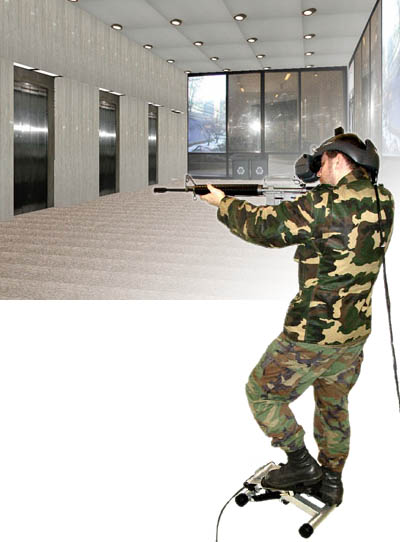 Figure 1. Photograph of the FootStepper in use in a VE walkthrough of building-36 at MIT (a bit of impromptu "building clearing" ).
2 HardwareThe FootStepper is based on a sturdy but inexpensive (about $100) exercise machine sold at www.brookstone.com (see figure 2). This unit was originally selected not only for its robust construction, but also for the simple adjustment of step amplitude and the integral dampers that appeared to be easy to modify. In addition, the unit includes a magnetic reed switch and magnet assembly for use by its built-in calorie counter. Further examination revealed that the reed switch arrangement was not adequate for our purposes and subsequently the switch and the built-in factory electronics were discarded. 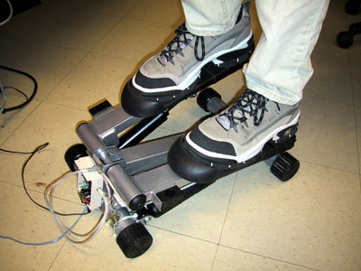 Figure 2. Close-up photograph of the FootStepper, which is based on an exercise machine sold at Brookstone (the StepFlex Compact Fitness Center Mini Stepper, Brookstone sku# 288209). The foot pedal position signals are derived from the action of a magnet (attached to the moving lever) on a linear Hall-effect sensor. Originally we used the factory-mounted magnet, but the position and strength of that magnet were not ideal at all of the possible step amplitudes that we wished to measure. Figure 3 shows the alternate arrangement that we have successfully used. Label "A" indicates the position of a powerful rare-earth magnet that we glued to the lever at the pivot sleeve, label "B" shows the position of the Hall-effect sensor mounting post (attached to the stationary base of the machine. The hall-effect sensor can be obtained directly from Allegro MicroSystems Inc. Our prototype used a UGN3503LU having a sensitivity of 1.3mV/Gauss (purchased from Newark Electronics), however this device has been superceded by newer models in different (smaller) packaging, as listed on the Allegro datasheet web page for the UGN3503 series of Unipolar Ratiometric Linear Hall-Effect Sensors. The Neodymium magnet (CR30812-37) was obtained from Edmund Scientific. 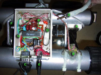 Figure 3. Photograph of control circuit and sensors. A: magnet, B: Hall-effect sensor, C: D9 serial interface connector, D&D': plug & jack for heel sensor, E: power input, F: reset pushbutton, G: IC's (Ubicom SX28 microcontroller & Maxim MAX233 RS232 buffer). The amount of effort required to perform each step on the unmodified machine turned out to be too great regardless of the adjustment of the amplitude control. To put the level of effort within a useful range for sustained walking, we considered removing the dampers completely. However, some amount of controlled resistance was desired in order to simulate the energy expenditure of walking as well as to assist in balancing while standing on the device. To modify the dampers we simply drilled two 3/16" holes near the end of each cylinder, as shown by the green arrows in figure 4. This operation was slightly messy since the damper is filled with silicone liquid, which we extracted by pumping the damper repeatedly until empty. A future enhancement to the system will be to add electronically-controlled valves to the damper in order to vary the damping factor under computer control (to simulate walking on hilly terrain). 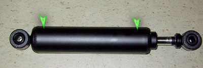 Figure 4. Photograph of damper piston. The arrows show location of drilled vent holes. The heel pressure sensor is shown in figure 5. The purpose of this sensor is to enable the software to determine when the user is walking backwards. This condition is detected when the user maintains higher than normal pressure on the heels while stepping. We are not totally convinced that this method feels as natural as we would like, but it is a workable solution until something better is developed. The pressure sensor was constructed using Xilor Inc. Zoflex ZF series pressure-sensitive conductive rubber sandwiched between a pair of aluminum sheets. We found it difficult to attach the conductive rubber to any material, so our method was to confine it from sliding around using cloth tape, then relied on the fact that it is not subject to any sheer or sliding forces. We have not noticed any sliding problems with this method, and upon removing the covering to take the photograph we discovered that the Zoflex material was still in the original configuration. 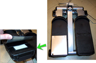 Figure 5. Photograph with detail of heel pressure sensor construction. A microcontroller and associated electronics are used to convert the analog signals from the step and heel sensors into serial data that can be accessed through a com port. Figure 6 shows the schematic of this circuit. The analog-to-digital conversion is performed in software based on the charge/discharge timing of the R/C networks attached to the C4 thru C7 pins. A dual-color common cathode LED was wired to pins B5 & B6 to allow for feedback to the user. Pins A1 and A2 provide serial I/O via the MAX233 buffer/converter chip. A three-terminal 50MHz resonator available from Parallax.(#250-15060 or #250-05060) was used to complete the clock oscillator circuit. The assembly code for programming the SX28 microcontroller is listed in the appendix. The software serves as a "software UART" for generating and receiving the serial I/O signals, does the timing and control to effect the analog-to-digital conversion, and also performs some built-in statistical calculations such as step amplitude, skew, and timing. Some of these latter features were not used (or were redundant) in our final VE walkthrough described in the next section, but were left in the listing because having these features "built into the interface" could be useful in other contexts. The code listing includes comments describing the protocol by which the host makes requests for status and statistics information (especially position of step and heel pressure).  Figure 6. Schematic diagram of controller, including serial interface and sensors (click to enlarge image).
3 SoftwareThe software used to interface the FootStepper to a virtual environment walkthrough was written in C for Windows NT. The walkthrough itself was generated using the Vega realtime simulation software from Multigen-Paradigm, Inc. As Windows NT is a relatively common platform for simulation, no attempt has been made to remove Windows-specific references in this section; however as Vega is a proprietary third-party API, Vega-specific code has been replaced with generic descriptions. The FootStepper software is separated into three modules: the serial communications drivers, a generic "motion model" for the user's viewpoint, and a dedicated FootStepper querying and processing engine. The communications module is typical of any that would be used to receive information from a motion tracker or other serial device, and is included in the Appendix primarily for the aid of other Windows NT users. The motion model is a thread that runs synchronously with the rendering engine. Before each frame is rendered, the motion model is queried for an update to the user's position. Once the user's viewpoint is updated, control is passed to the rendering system which generates the frustum and draws the scene. As this process is independent of the specific nature of events, such as locomotion, affecting the user's position, the motion model was implemented in a generic fashion such that it relies on only two input variables, the rate of linear motion (forward or backward) and the amount of rotational motion (turning left or right). This also renders the motion model immune to adjustments to FootStepper processing algorithms, and allows the possibility of on-the-fly selection of alternative ground-based locomotion schemes. The two input quantities are global variables protected by a mutex (mutual exclusion semaphore). The exact values of the variables are relative to a pair of constant base moving and turning velocities. As the motion model code is highly Vega-specific, a pseudocode description of the entire update query procedure is presented as follows: Pre-frame update:
Wait for stepper variable mutex
Copy global step and skew variables into local variables:
step_apply = step;
skew_apply = skew;
Release stepper variable mutex
Subtract gravitational descent from vertical position:
user_z = user_z - gravity;
Compute new heading based on skew variable and time since last frame:
user_heading = user_heading - (turn_speed * skew_apply * dt);
Compute new position based on new heading, step variable and frame time:
user_x = user_x - (base_velocity * directional_sine * step_apply * dt);
user_y = user_y + (base_velocity * directional_cosine * step_apply * dt);
Query collision detection intersectors
Readjust user position based on collision information
Return
The FootStepper-specific processing is performed in a separate thread that runs asynchronously other than accepting and releasing the mutex once per cycle to ensure that minimal delay is imparted to the motion model. Each cycle, the thread queries the FootStepper for the most recent local maximum and minimum foot positions, the current position, and the status of the backwards attitude sensor. From these values the most recent step amplitude is calculated as the difference between the maximum and minimum positions, while the skew is calculated as their average. If the foot position is within five percent of the appropriate maximum or minimum (depending on whether a right or left footfall is being recorded), then a step is registered. It should be noted that this generates a step having the previous step amplitude; this was considered acceptable in order to enable the user to take single steps, which was identified as an important form of small-scale maneuvering. If the true local maximum or minimum were to be insisted upon, in order to register a completed step the user would have to generate a physical inflection corresponding to the beginning of a second step. In any case, the perceived difference between real and virtual step sizes over a single step seems small at worst. If a step is recorded on the current cycle, the procedure determines whether it is a walking or turning step, according to the value of the skew. If a walking step, the value of the back attitude sensor is compared with a threshold and the step amplitude negated if it is determined to be a reverse step. The step amplitude is then fed into the appropriate accumulator to adjust the current step rate or turn speed. A decelerator also provides negative feedback to each accumulator, to rapidly bring the user to a halt when stepping ceases. If the position value has been updated over the past cycle, even if a step has not been recorded, the decelerators are temporarily disabled to smoothen the velocity during continuous walking. A complete listing of the FootStepper processing code is included in the Appendix. The FootStepper software currently supports only linear motion and turning in place as priority was given to preventing the registering of undesired turns, in order to make the interface as robust as possible for novice users, especially given the added task of maintaining balance while wearing an HMD. In addition, it is clear from the description above that there is an important latency present in the interface. Some latency is inevitable in any virtual environment locomotion interface, as the device must spend time recording and interpreting users' movements in the real world before updating their virtual location and scene view. The principal latency inherent in the FootStepper is that no update to the user's velocity and hence perception of motion is initiated until the first complete step has been recorded. This was necessary due to the use of a single modality for both position and orientation control -- during the first moments of a step, the system has no way of determining whether the step is symmetric or asymmetric, and thus whether the user intends to move or turn. This latency does not seem overly distracting, and the reduced amount of cognitive overhead and coordination required through the reliance on a single modality led us to consider this trade-off acceptable. AcknowledgementsThis work was performed with support from ONR
grants N00014-96-1-0379 and ReferencesChristensen, R., Hollerbach, J.M., Xu, Y., and Meek, S. (2000). "Inertial force feedback for the Treadport locomotion interface." Presence: Teleoperators and Virtual Environments, Vol. 9, No.1, pp. 1-14. Fitch, S.B. (1998). The Finger Walker: A Method to Navigate Virtual Environments. M.Eng. Thesis supported by ONR grant N00014-96-1-0937. Cambridge: Massachusetts Institute of Technology. Iwata, H., & Fujii, T. (1996). "Virtual Perambulator: A Novel Interface Device for Locomotion in Virtual Environment." IEEE Proceedings of VRAIS'96, pp. 60-65.
AppendixCode listing for Ubicom SX28 micontroller (click here). Serial code listing (click here). Step monitor thread code listing (click here). |