The bit assembly embodies the state of the knex-i-comp. It's analogous to the Digi-Comp I's flip-flop. There is one bit asembly per bit frame.
In the knex (tm) model, each bit is implemented by an assembly of gray struts and yellow (arity 5) connectors. The assembly is hung from an inverted pendulum formed from a pair of arms constructed from two gray (arity 1) connectors coupled together by a green strut. The inverted pendulum ensures that the bit assembly will rest in either of the two extreme positions of its motion and is not stable anywhere in between. This provides hysteresis, which is necessary in all digital logic systems.
The bit assemblies of a single bit connect end-to-end with one another, sharing the yellow connector inverted pendulum assemblies with their neightbors.
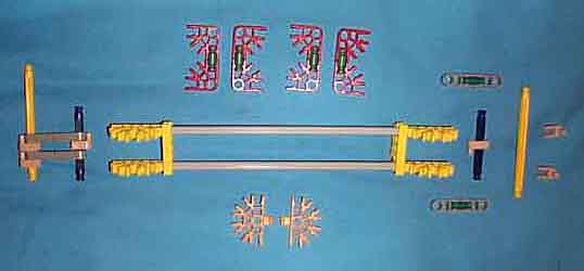
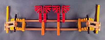
Above is a picture of a partially assembled bit assembly. In the picture below it is fully assembled.
The yellow struts to which the inverted pendula (pendulums?) attatch are from the ends of the bit frame.
The yellow (arity 5) connectors which are parallel to the yellow mounting strut, in addition to holding gray struts of the bit assembly together, also serve to stop the inverted pendulum from swinging too far to either side. That is why they are slid up against the inverted pendulum assembly instead of being anywhere along the bit assembly.
The positioning of the programming hardware will need to be adjusted after the bit assembly is installed in the bit frame and the sense rods are in place.