The bit frame is the structure on which all of the logic elements are mounted. There is one bit frame for each control stage (connected horizontally) and one for each bit (connected vertically), so the number of bit frames is the product of the number of bits and the number of control segments.
Bit frames comprise a substantial portion of the structure of the knex-i-comp.
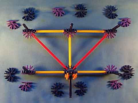
Next to each blue/purple composite connector are shown the connectors which are put together to form it, in their approximate orientations in the structure.
Only one bit frame in a given control stage needs to have the two orange clips. These merely serve to prevent the actuator reods from unhinging when the knex-i-comp is tilted or inverted.
The bit frame will also have a ywllow strut at each end, connecting the top and bottom corners together. These struts are not shown here since it is easier to assemble the bit assembly directly onto these struts before they are in place.
The bottom-most bit frame, which mounts on top of the control frame, does not have the blue strut which sticks out in the bottom of the picture.
The two front corners (lower edge of the picture) of the bottom-most bit frame consist entirely of blue connectorsather than blue/purple pairs. These provide attatchment points for the front upper level of the control frame.
The upright blue struts will connect up to the next level.
For multiple control stages, the bit frames connect end-to-end with each bit frame sharing the blue and purple connectors at their corners with their neighbors.
The upright white struts will serve as the hinge pins on which the actuator rods swing.