|
Observing Manual
Before your run
You may prepare exposure time estimates using the zero point graphs located on the Specifications page
Your other task is to prepare your observing catalog. The catalogs should be formatted in the standard Magellan fashion, which is documented here.
An always-cryptic field in the catalog is the instrument-specific rotator angle. The value you should use depends on whether you are observing in longslit or echelle mode, since changing modes requires rotating the slit by 90 degrees inside the instrument.
Most users will want to orient the slit along the parallactic angle. To achieve this, in fields 8 and 9 in the catalog file, you should use the following values:
Echelle mode: -0.2 HRZ
Longslit mode: 89.8 HRZ
If you would like to orient the slit along a particular position angle, replace these fields with the following
Echelle mode: [PA-0.2] EQU
Longslit mode: [PA+89.8] EQU
Afternoon startup
When you arrive in the afternoon, the instrument specialists should have powered on the instrument and detectors. Log on to Burro (currently Llama is not suppoerted for FIRE observations) and start the FIRE software by opening a terminal and typing "fire" at the command prompt. Likewise, from a Burro terminal you can start the guider software by typing "fg" (i.e. fire guider) at the command prompt.
The initial window will prompt you to enter the observers' names. It also allows you to change settings pertaining to what items are monitored and IP addresses of various hardware. Do not turn on temperature monitoring and control; this software is running offline 24/7 on a separate instrument-only workstation so you do not want to start a duplicate compy on Burro. Also, do not change the IP addresses from their default values.
The check boxes at the right of the window are used to launch different modules of the software suite. Observers should only launch the camera control and telescope interfaces. Enter your name and click "OK" to launch the FIRE GUI. The telescope control window must be activated to ensure that time stamp and position information from the TCS is written into FITS headers.
Instrument control GUI
The observer control GUI consists of an instrument control, a telescope monitor, and a log window. You only need interact with the FireEngine control window. In addition you will launch a guider applcation, described below. The following subsections explain the various options and interactions required.
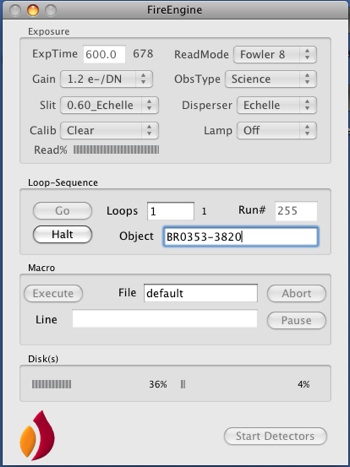
Exposures are started with the "Go" button. A simple macro functionality is built into the instrument or calibration sequences. Exposure loops were not supported for early operations but are working properly for 2011A. Macros are not currently supported.
Detector Gain
FIRE offers two different gain settings for the spectrograph detector, as shown in the table below.
| |
Conversion Gain |
e- Read noise [Amps 1,2,3,4] |
Saturation Level |
| High gain |
1.3 e- / DN |
[20,16, 22,17] |
~ 20,000 ADU |
| Low gain |
3.8 e- / DN |
TBD |
~ 32,000 ADU |
For most observations, users should select "High gain" mode. This offers the most sensitivity and lowest noise. However, for bright objects where dynamic range is a concern, users may wish to operate in low gain mode to utilize the entire full well of the detector. Note that in high gain mode the electronics saturate well below the full 65,000 count range to which users may be accustomed. In low gain, the count rate saturates at 32,000 ADU, but at 3.8 e-/DN this captures the entire full well capacity of FIRE's HAWAII-2RG detector. In high gain the detector is completely linear until saturation, while in low gain a substantial non-linearity sets in above 28,000 counts.
The noise values quoted are for a single double correlated sample read, equivalent to Fowler-1.
Readout Modes: read noise vs. overhead
The FIRE spectrograph detector may be read out in one of several modes. Unlike CCDs, IR arrays are read out non-descructively, so that the pixel charge may be sampled multiple times. This is generally desriable since multiple readouts reduce the read noise by ~1/sqrt(N), and read noise is significant for spectroscopy. However there is an overhead penalty for large numbers of reads, since each individual read takes approximately 10 seconds.
FIRE offers two main modes for taking science data: Fowler sampling, and Sample-Up-The-Ramp.
In "Fowler N" mode, the detector is read N times before the start of the exposure, then the software waits for the requested exposure time, and then it reads again N times again at the end of the exposure. The pre-integration and post-integration reads are averaged together respectively, and the image signal is the difference between these averaged groups. Since the detector is read 2N times, the total readout overhead is 2N * (10.6 seconds), in addition to the requested exposure time.
In SUTR or Sample-Up-The-Ramp mode, the detector is read out continuously during the exposure at regular cadence. At conclusion, the software fits for the slope of charge accumulated as a function of elapsed time to estimate the science signal. This provides the benefits of many reads (i.e. reduced read noise) with much smaller overhead at the start and end of the exposure. The drawback is that exposure times are limited to an integer multiple of the array readout time (10.6 seconds).
The graphs below show measurements made of the read noise in Fowler-N and SUTR read modes for the FIRE detector read out in the high gain mode (1.3 e-/DN). At left, we show the noise in electrons per pixel for SUTR integrations of various lengths. The overhead is fixed at roughly 30 seconds for any SUTR read. At right, we show the noise as a function of pair count for Fowler sampling. In this case, the noise goes down but the overhead time (shown at top of the graph) increases linearly with pair number. For exposure times >600 seconds, noise performance approaching that of Fowler-8 is achieved with much smaller overhead using SUTR, and most users will want to operate in this mode.
The FIRE software only returns a single (slope * integration time) image for SUTR reads, with no cosmic ray rejection. Algorithms exist to reject cosmic rays given a full image cube. If users request this information we may provide utilities to access the raw detector reads but for now this is not provided as a default option.
Several other readout modes are listed in the GUI pull-down menu, but these are for engineering purposes only and should not be used for science data acquisition.
Exposure Times
Exposure times are entered into the GUI in the normal fashion; hit return to be sure it registers.
FIRE does not have a mechanical shutter, instead it starts exposures throguh an electronic reset of the detector. As a consequence, the exposure time you enter in the GUI is not necessarily the same as what you would get with a traditional shutter-based CCD. It also means that users cannot pause and resume integrations mid-exposure.
When using Fowler sampling, the exposure time entered in the GUI is the time elapsed between the initial and final reads of the detector. Since light falls on the detector as it is being read, the effective exposure time is longer than the entered time by exactly one readout time, or 10.6 seconds. This also sets the effective miminum exposure time for the spectrograph to 10.6 seconds. This should be kept in mind when scaling exposure times for flat fields, standards, and other bright objects. The 10.6 second rule applies regardless of the number of Fowler samples, i.e. a Fowler-2 image also has a minumum exposure time of 10.6 seconds, not 21.2 seconds.
For SUTR sampling, the exposure time must be a multiple of 10.6 seconds. The GUI will automatically force the exposure time entered into the box to the nearest legal SUTR integration that is >= the time requested. For very long exposures, the number of SUTR samples can become quite large with no discerable improvement in noise performance. In this case, to keep the data flow manageable the software reads out in integer multiples of 10.6 seconds (i.e. every 21.2, 31.8 etc seconds) when it can do so without compromising noise performance.
Slit Selection
FIRE has a slit wheel with 10 positions. One slot is used for a pinhole focus mask, and one contains an opaque blank. This leaves four slits apiece for echelle and longslit modes. The slits are oriented at right angles for the different modes. The echelle slits are 6 arcseconds long and oriented from left-to-right on the slit viewer. The long slits are 1 arcminue in length and oriented top-to-bottom.
Slits are selected from the pull-down menu in the GUI. We have observed positional repeatability of roughly 0.15", or one pixel in slit moves. Occasionally the wheel fails to reach its position detent, as can be seen from error messages and / or an uncentered slit image in the slit viewing camera. It is good practice to take a slit view image after slit moves to verify positioning. If a move fails, move to another slit position and then back to the desired position. To date, this has always yielded a successful move on the second attempt. If this fails, contact an instrument specialist for help.
For echelle mode, the slit center should fall near the position x=168, y=192 on the slit view camera, within a few pixels. The x position should be perectly repeatable, but the y position moves slightly on slit changes.
Dispersers
The disperser mechanism is a binary unit which swaps between the echelle grating and the low-dispersion mirror. It is activated from a GUI pull-down menu. Disperser changes are slow and require approximately 90 seconds to complete.
Calibration options and suggested sequences
A full sequence of spectral calibrations includes pixel flat fields, wavelength calibrations, and illumination (sky) flats. The instrument contains a set of internal calibration lamps, these provide good calibrations for echelle mode. For longslit observations, the internal lamp does not provide very uniform illumination; the dome screen is a better choice for flats and arcs in this mode.
It is advisable to take twilight flats to calculate the slit illumination function, for accurate sky subtraction. In a pinch, dome flats may be used in echelle mode for illumination correction.
Echelle Calibrations
To take internal calibrations, you must insert a mirror into the beam, and turn on your lamp of choice. These are two separate actions, and must be undone at the end of the sequence. The mirror is inserted via the "Calib" pull-down menu. A value of "mirror" inserts the calibration mirror, "Clear" removes the mirror for science observations.
FIRE's foorptint includes two orders with relatively few lines for wavelength calibration in echelle mode. It is therefore critical if your science exposures will be <8-10 minutes to obtain arcs of sufficient depth to bring out several lines. This is an important part of the pipeline since a proper fit to the tilt and curvature of the orders is needed to perform both wavelength calibration and sky subtraction. We have had good success with 10 second ThAr lamp exposures with a 0.6" slit; it should be OK to go even longer so long as most lines are not saturated.
Wavelength: For exposures longer than 8-10 minutes, an accurate wavelength calibration may be obtained using OH lines from the night sky. For shorter exposures, particularly for flat fields and telluric standards, the ThAr lamp should be used to take a concurrent wavelength calibration. We recommend to take an arc at every pointing, since the instrument does flex at the 1 pixel level with different gravity orientations. Some orders do not have many lines from the ThAr lamp. When in doubt, err on the side of long exposures to bring out weak lines, even if the strong lines saturate.
Flat fields: These must be kept below 18,000-20,000 counts to avoid saturation effects in high gain mode. For a 0.6" slit, 1 second with the internal Qh lamp produces reasonable count rates. For wider slits, a Ql lamp is available which has lower flux levels to avoid saturation. Remember, when scaling flat exposure times in Fowler mode, the actual exposure time is (10.6 + texp) seconds, where texp is the value in the exposure time GUI.
The following table summarizes calibration sequences that have worked well during commissioning. Use at your own risk, especially in the shared-risk phase as we are learning best calibration practices in conjunction with pipeline development.
FIRE Recommended Echelle Calibrations
| Slit |
Qh Flat |
Ql Flat |
ThAr |
| 0.45 |
1-7 sec, Fowler 1 |
Adjust as needed |
30 sec Fowler 1 |
| 0.60 |
1 sec, Fowler 1 |
Adjust as needed |
10 sec Fowler 1 |
| 0.75 |
Saturates |
40 sec |
5 sec Fowler 1 |
| 1.00 |
Saturates |
20-30 sec |
2 sec Fowler 1 |
Long slit calibrations
For longslit observations, dome calibrations with the flat field screen should be used rather than internal lamps. For flat fields, we use the variable quartz lamp whose power supply is in the dome. Generally, two flats are needed at different voltages, to get adequate counts across the full spectral range. A high voltage flat (2.0-2.2V) is used to get counts in the z and J bands, but saturates in H/K. A low voltage flat (1.0-1.2V) is used to calibrate H and K, but is too faint for the blue end. The FIRE longslit reduction software takes these two flats and splices them together for a final superflat.
For wavelength calibration, you may use either the night sky lines (which are substantially blended), or else arc lamps. After expermentation with various combinations of flat field lamps, we recommend using a combined NeNeAr setup (both Ne lamps, on Ar on the flat field screen). This balances line strengths nicely.
Selecting Telluric Standards
It is best practice to observe A0V telluric standard stars between science objects, to calibrate atmospheric absorption features. These observations are also used to perform flux calibration by the reduction software. We have installed a tool at the telescope (on the workstation burro) which assists users in selecting tellurics from a large list of A0V standards.
To run the tool, go to the directory /Users/fire/python and enter "source python_setup", just once to get the session started. Then, for each field required, run the following:
find_tellurics --RA 14:47:17 --DEC +04:01:12 --UO 08:50 --UT 09:25
The program, find_tellurics, takes the following inputs:
-RA, DEC - The right ascension and declination of your science target
-UO - The central UT time of your science target observation (note this is the letter "O", not a zero)
-UT - The expected UT central time of observation for the telluric standard
The software will output a list of stars which are the closest match in airmass and sky angle:
Object: RA= 14:47:17, Dec= +04:01:12 airmass= 1.372 at lst 16:43:14
Best telluric matches:
(1): HD123309 ----- Magellan Catalog Number: 10215
Mag= 9.40 (Band= V) RA= 14:07:24 Dec= -23:28:29 Anguler Offset= 29.16 deg
This telluric: airmass = 1.364 at lst 17:18:14 airmass diff from source = 0.007. Match rating = 54.18
(2): HD125062 ----- Magellan Catalog Number: 10249
Mag= 9.98 (Band= V) RA= 14:17:29 Dec= -19:29:07 Anguler Offset= 24.62 deg
This telluric: airmass = 1.346 at lst 17:18:14 airmass diff from source = 0.025. Match rating = 30.37
(3): HD123426 ----- Magellan Catalog Number: 10217
Mag= 9.66 (Band= V) RA= 14:08:10 Dec= -24:33:51 Anguler Offset= 30.12 deg
This telluric: airmass = 1.354 at lst 17:18:14 airmass diff from source = 0.018. Match rating = 27.47
The "Match rating" field is a figure of merit for the quality of telluric match, and should be as large as possible with maximum 100.
Once you've selected from the list presented, the telescope operators have the catalog file of all FIRE A0V calibrators available in FIRE_tellurics.cat. It is a long list, so you should specify the star by its catalog object number rather than name. The object number is listed above in the field "Magellan Catalog Number."
Note that the catalog orients the slit in the parallactic angle for ECHELLE mode. If you are using Longslit, you should advise the TO to rotate the instrument 90 degrees.
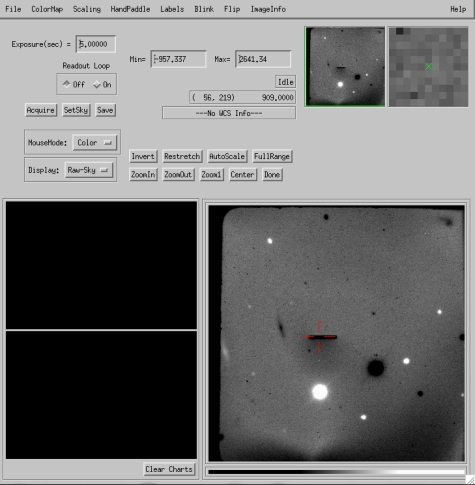
The FIRE slit viewer
FIRE's slit viewer is controlled by the observer. It has a field-of-view of approximately 1 arcminute with 0.147" pixels, and utilizes a fixed MKO J band filter.
To start the slit viewing software, from a unix terminal on burro, type "idl" and then "fg". This should bring up the window shown below. The software IDL-based, and is derived from the atv software package distributed freely by Aaron Barth.
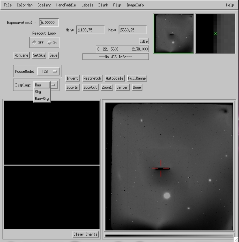
The user's main interactions are to change the exposure time, take frames, set the slit location, and move objects onto the slit. Generally the slit viewer is used for object acquisition, and the observatory guiders perform actual guiding functions. However, the slit viewer may be operated independly during long integrations with the spectrograph, to check the location of the object on the slit and perform adjustments if needed.
To take a slit image, press the "Acquire" button. The detector will expose for the requested duration and auto-display the image. Press the auto-scale button to scale the image stretch, and use the mouse (left button) to achieve the desired contrast. Though not shown in the image above, at the telescope the display will include a compass rose and scalebar to aid in orienting the field.
Specifying the nominal slit position: Before starting your spectroscopic observations, you should specify the pixel that will be the defined "A" dither position on the slit. It should be offset by 1-1.5" to the left of the slit center in echelle mode to allow dithering by ~2". In longslit mode, 5" below the slit center is appropriate. Under "MouseMode," choose the "Slit" option and left-click on the pixel where you'd like to place the slit. A crosshair will indicate the location of your selection.
The mouse can only enter integer pixel positions for the slit. If you want finer control over position, you may enter any value by hand. To do this, from the IDL command line, type "fatv_slit, <x>, <y>" where <x> and <y> are the desired positions, which may be fractional pixels.
Putting objects on the slit: When your slow completes, take a test image. Locate your object, select the "TCS" mouse mode, and left-click on the object to move it to the slit. You will be prompted for approval before performing a telescope move. It is usually the case that an additional small move (0.1-0.5") is needed to precisely position your target on the slit. See the "handpadde" instructions below for information about how to perform fine moves.
Saving images from the slit viewer: It is often useful to save images from the slit viewer for later analysis. To do this, click the "Save" button. This will open a dialog box which prompts you for where to write a fits image containing header information about the pointing center and rotation angle.
Displaying sky subtracted images: For faint objects it is often helpful to take images at two dither positions and difference them to suppress the sky. The guider has a built in function to do this, operated as follows. First, take an exposure that will serve as the sky reference. When it appears on the screen, click "SetSky." This will load that frame into a separate image buffer reserved for the background frame. Then, move the telescope to the target position and take another frame. When the new frame appears, go to the "Display" pull-down menu and select "Raw-Sky." The display window will now show the raw image just obtained minus the sky buffer you saved previously. To switch back to displaying the raw read, simply change the display pull down menu value. An example of a sky-subtracted image is shown below; note that objects on the sky frame will appear as negative images on the Raw-Sky display mode.
There is a known bug in which the compass rose sometimes disappears from the frame in Raw-Sky mode. We are working to fix this. In the interim, operating in "Raw" mode should work if your observations can support this.
Dithering your target along the slit: A simple idl script may be executed from the IDL command line to dither objects on the slit between two different positions. After completing your first observation, at the prompt, type:
IDL> fatv_abba, /b
to move the object 2.5" to the right in slit in slit viewer coordinates. To move from the "B" position back to "A", type
IDL> fatv_abba, /a
If you wish to move by an amount other than 2.5", you may do so. For example, for a 2.0" dither length, type:
IDL> fatv_abba, /a, dist=2.0
By default the dither macro assumes you are in echelle mode. If you are observing in long slit mode, add the "/ls" keyword to dither up and down in slit viewer coordinates, rather than right to left as you would for echelle slits.
Measuring seeing or counts on the slit: The ImExam Mouse Mode may be used to perform rudimentary analysis of image quality. Select this using the pull down menu and then left click on a star to measure its FWHM in pixels. Remember that the pixel scale is approximately 0.147".
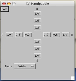
Performing small dithers by hand: Occasionally users may want to perform small offsets or corrections to the pointing in the vicinity of the slit. There is a Virtual Handpaddle widget in fatv built for this purpose. From the top menu bar, select "HandPaddle" to bring up the widget. Offsets are sent by default in the coordinate system of the guide camera, with the software calculating the correct rotation into RA and DEC. If you wish to send offsets directly in RA and DEC, change the "Basis" menu from Guider to Equatorial. For guider offsets, we move the telescope, not the universe. So, clicking "down" on the handpaddle moves the telescope/slit down, or the object up in guider coordinates.
Blind Offset Pointing with FIRE
For objects not visible in the slit viewer, you must perform blind offset pointing from nearby bright stars. In 30 second integrations on the guider in 0.6-0.7" seeing it is possibe to see point sources with J>20 on the slit viewer. Fainter targets may need a blind offset.
To perform a blind offset, first place the reference star on the slit as you would any bright target.
The simplest method is then to tell the telescope operator the offset in RA and DEC. The offset parity should aim FROM the reference star TO the science object.
If you prefer to enter in the offsets yourself, you may do so, by entering "fatv_blindoffset, dra, ddec" at the command line, where dra is the RA offset in arcseconds East, and ddec is the DEC offset in arcseconds North. This sends the same command that would be executed by the telescope operator.
|