12.5 Velocity Triangles for an Axial Compressor Stage
Velocity triangles are typically used to relate the flow properties
and blade design parameters in the relative frame (rotating
with the moving blades), to the properties in the stationary or
absolute frame.
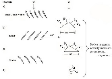
We begin by ``unwrapping'' the compressor. That is, we take a
cutting plane at a particular radius (e.g. as shown in Figure 12.4)
and unwrap it azimuthally to arrive at the diagrams shown in
Figure 12.6. Here we have assumed that the
area of the annulus through which
the flow passes is nearly constant and the density changes are small
so that the axial velocity is approximately constant.
Figure 12.6:
Velocity triangles for an axial compressor stage. Primed
quantities are in the relative frame, unprimed quantities are in the
absolute frame.
|
|
In drawing these velocity diagrams it is important to note that the
flow typically leaves the trailing edges of the blades at
approximately the trailing edge angle in the coordinate frame
attached to the blade (i.e. relative frame for the rotor, absolute
frame for the stator).
We will now write the Euler Turbine Equation in terms of stage
design parameters:  , the rotational speed, and
 , the leaving angles of the blades.
From geometry,
and
so
or
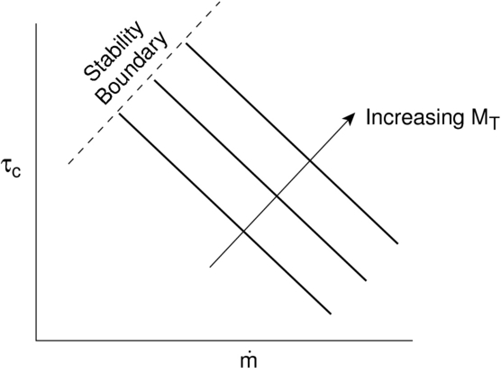
So we see that the total or stagnation temperature rise across the
stage increases with the tip Mach number squared, and for fixed
positive blade angles, decreases with increasing mass flow. This
behavior is represented schematically in Figure 12.7.
Figure 12.7:
Compressor behavior
|
|
UnifiedTP
|
![$\displaystyle \underbrace{\frac{T_{Tc}}{T_{Tb}}}_{\substack{\textrm{stagnation ...
...}_{\substack{\textrm{$\beta$'s set by} \textrm{blade design}}}\right)\right].$](img1579.png)