VIII. Ideal Cycle Analysis of Aircraft Gas Turbine Engines
A. Introduction
In thermodynamics we represented a gas turbine engine using a Brayton cycle, as shown in Figure 8.1, and derived expressions for efficiency and work as functions of the temperature at various points in the cycle. In this section we will perform “ideal cycle analysis”, which is a method for expressing the thrust and thermal efficiency of engines in terms of useful design variables. If you take a further course in propulsion, this ideal cycle analysis will be extended to take account of various inefficiencies in the different components of the enginethat type of analysis is called non-ideal cycle analysis.
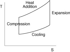
Figure 8.1 Schematic of a Brayton cycle.
1. Objective of ideal cycle analysis
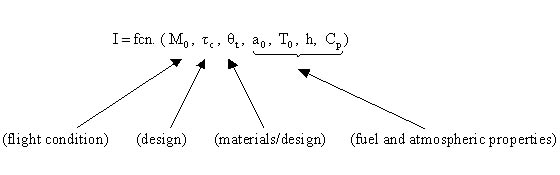
Our objective is to express thrust, T, and thermal efficiency, h (or alternatively I) as functions of 1) typical design limiters, 2) flight conditions, and 3) design choices so that we can analyze the performance of various engines. The expressions will allow us to define a particular mission and then determine the optimum component characteristics (e.g. compressor, combustor, turbine) for an engine for a given mission. Note that ideal cycle analysis addresses only the thermodynamics of the airflow within the engine. It does not describe the details of the components (the blading, the rotational speed, etc.), but only the results the various components produce (e.g. pressure ratios, temperature ratios). In Section IX we will look in greater detail at how some of the components (the turbine and the compressor) produce these effects.
![]()
![]()
2. Notation and station numbering
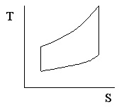
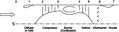
Figure 8.2 Gas turbine engine station numbering.
Notation:
![]()
![]()
![]() (
(![]() )
)
Stagnation properties, TT & PT, are more easily measured quantities than static properties (T and p). Thus, it is standard convention to express the performance of various components in terms of stagnation pressure and temperature ratios:
p º total or stagnation pressure ratio across component (d, c, b, t, a, n)
t º total or stagnation temperature ratio across component (d, c, b, t, a, n)
where d= diffuser (or inlet), c= compressor, b= burner (or combustor), t= turbine, a= afterburner, and n=nozzle.
3. Ideal Assumptions
1) Inlet/Diffuser: pd = 1, td = 1 (adiabatic, isentropic)
2) Compressor or fan: tc = pcg-1/g , tf = pfg-1/g
3) Combustor/burner or afterburner: pb = 1, pa = 1
4) Turbine: tt = ptg-1/g
5) Nozzle: pn = 1, pn = 1
Check out the Thermo notes for a refresher on cycle analysis done in the fall - GO! |
B. Ideal Cycle Analysis Example: Turbojet Engine
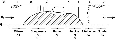
Figure 8.3 Schematic with appropriate component notations added.
NASA Glenn has a great interactive web program for gas turbine engine analysis - GO! |
Methodology:
1) Find thrust by finding uexit/uo in terms of qo, temperature ratios, etc.
2) Use a power balance to relate turbine parameters to compressor parameters
3) Use an energy balance across the combustor to relate the combustor temperature rise to the fuel flow rate and fuel energy content.
First write-out the expressions for thrust and I:
![]() where f is the fuel/air mass flow ratio
where f is the fuel/air mass flow ratio
 (can neglect fuel)
![]()
That is the easy part! Now we have to do a little algebra to manipulate these expressions into more useful forms.
First we write an expression for the exit velocity:
Noting that
![]()
We can write
Thus
![]() (*)
(*)
Which expresses the exit temperature as a function of the inlet temperature, the Mach number, and the temperature changes across each component. Since we will use this expression again later we will mark it with an asterisk (*).
We now write the pressure at the exit in a similar manner:
and then equate this to our expression for the temperature (*)
 (**)
(**)
and again label it (**) for use later as we do the following expression:
![]() (***)
(***)
We now continue on the path to our expression for u7/uo.
![]()
Therefore
Now we have two steps left. First we write tc in terms of tt, by noting that they are related by the condition that the power used by the compressor is equal to the power extracted by the turbine. Second, we put the burner temperature ratio in terms of the exit temperature of the burner, (TT4 or more specifically qt=TT4/To) since this is the hottest point in the engine and is a frequent benchmark used for judging various designs.
The steady flow energy equation tells us that
![]()
Assuming that the compressor and turbine are adiabatic, then
![]() = - rate of shaft work done by the system = rate of shaft work done
on the system
= - rate of shaft work done by the system = rate of shaft work done
on the system
Since the turbine shaft is connected to the compressor shaft
![]() assuming
assuming ![]() and
Cp are the same
and
Cp are the same
This can be rewritten as
 where
where ![]()
so
![]() or
or ![]()
That was the first step relating the temperature rise across the turbine to that across the compressor. The remaining step is to write the temperature rise across the combustor in terms of qt=TT4/To.
![]()
and for an engine with an afterburner
![]()
Now substituting our expressions for tb, and tt into our expression for u7/uo, and finally into the first expression we wrote for thrust, we get:
 Specific thrust for a turbojet
which is what we were seeking, an expression for thrust in terms of important design parameters and flight parameters:
![]()
With algebra 
We may write this write in another form which is often used
Our final step involves writing the specific impulse and other measures of efficiency in terms of these same parameters. We begin by writing the First Law across the combustor to relate the fuel flow rate and heating value of the fuel to the total enthalpy rise.
![]()
and
![]() where again, f is the fuel/air mass flow ratio
where again, f is the fuel/air mass flow ratio
So the specific impulse becomes
 Specific Impulse for an ideal turbojet
where I is expressed in terms of typical design parameters, flight conditions, and physical constants
 or
or