

2.00b Toy Product Design
Thermometer Step-by-Step

Here are the step-by-step instructions for building and testing the version of your thermometer that connects to your laptop!
You'll use this version for your daily 2.00b wellness check, as described in Lecture 2, let's get building, until you have your 3D printed housing design. Then, we'll give you instructions for using the components that will fit in the housing, along with how to mount the components.
These instructions assume no prior experience with building electronics or using a microcontroller. If you've done a bit of work with electronics or a microcontroller in the past, you may skip or skim through the explanatory sections. The explanatory sections will be very basic since it is not our goal in this project to teach programming or electronics. Initially, we just want everyone to be able to follow the step-by-step instructions and get the project to work.
You do not need to complete all the steps in one sitting. Feel free to take a break and come back to finish the project at a later time. You should aim to complete this project by the end of the week.
Getting help
2.00b staff will be monitoring the Slack #ask-the-tas channel for questions. There's usually someone available, even late at night. If not, take a break and come back to it when we've had a chance to answer your question.
Don't be shy to ask for help! For this project, if something has you stumped for more than 5 minutes, please reach out for help. Also, if you know the answer to a question that has been asked, please feel free to pitch in and answer. We're all in this together!
If the question is hardware-related (i.e., electronics), it is often helpful to post a picture of your wiring so that we can check that everything has been wired correctly. It may take multiple pictures from different angles to show all the wiring clearly. Sometimes a second set of eyes is all you need.
If the question is software-related, it is often helpful to post a picture of the error message.
If you don't know if the issue is hardware- or software-related, a good place to start is by posting your wiring and any error messages.
In all cases, when asking for help, please state clearly what the issue is. Stating "it doesn't work" is not helpful. Describe what is happening (or not happening), what you were expecting to happen, and what you have tried so far to fix the problem.
The Circuit
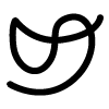
The circuit that we will be building for this initial iteration is shown below.
The parts that we will be using are:
- a microcontroller - Arduino Nano 33 IOT
- an IR temperature sensor module - MLX90614 on breakout board GY-906
- a display module - Adafruit 1.14" 240x134 Color TFT Display
- a push button - breadboard-friendly tactile switch
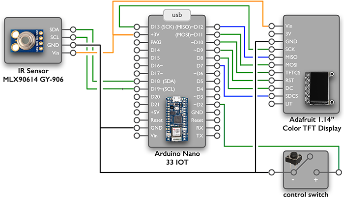
A pinout for each component is shown above along with a picture of the component. (Note, the full pinout for the Arduino Nano is available from its documentation.) A pinout is a diagram that lists all the pins of a component labeled with their names. The names usually give a hint as to the function of the pin, and we can refer to component documentation (linked above) for more details.
The GND pin should always be connected to the ground for the circuit. The Vin or VIN pin is for the positive power supply to the component. For this version of the circuit, power will be supplied to the microcontroller through the USB cable connected to our computers. The microcontroller provides an output voltage of 3.3V at the +3V pin, which is used as the positive power supply for the other components in our circuit.
On the microcontroller, the pins beginning with D are digital pins, and can be used as input pins (carrying data to the microcontroller) or output pins (sending data from the microcontroller). Digital pins read or provide signals that are either HIGH or LOW. This is in contrast to analog pins which may read or send a continuous range of values. Some pins handle both types of data. On the Nano, pins D14-D21 are also known as pins A0-A7, respectively, since they can handle analog data as well.
Our Process
We will be adding each component to the breadboard, one at a time. After each component is added, we will first test it alone and then as part of our overall project.
The steps we will follow are:
- Set up computer for programming
- Test the microcontroller
- Take temperature
- Deliver user feedback
- Add user input
- Connect to the internet (available Friday)
- Calibrate the system
Once this is done, we will have a working thermometer that can send temperature readings to the 2.00b database.
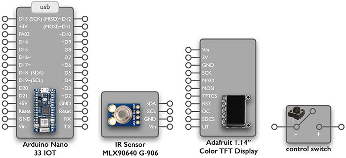
When our 3-D printed housing is ready, we will move the circuit to the smaller breadboard and use our additional components:
- a push button to replace the tactile button
- a battery to provide portable power
- a switch to turn the battery power on and off to the microcontroller
Let's get started!
Note: The videos in on the following pages "show", not "tell"! That is, there is no audio.