

User Experience
We set out to build something that was very interactive, and we were inspired to take a more typical assembly puzzle and make it reset-able. We wanted to make adventurers feel like they were interacting with a futuristic robot and fully immersing themselves in our sci-fi adventure.
Storyboard
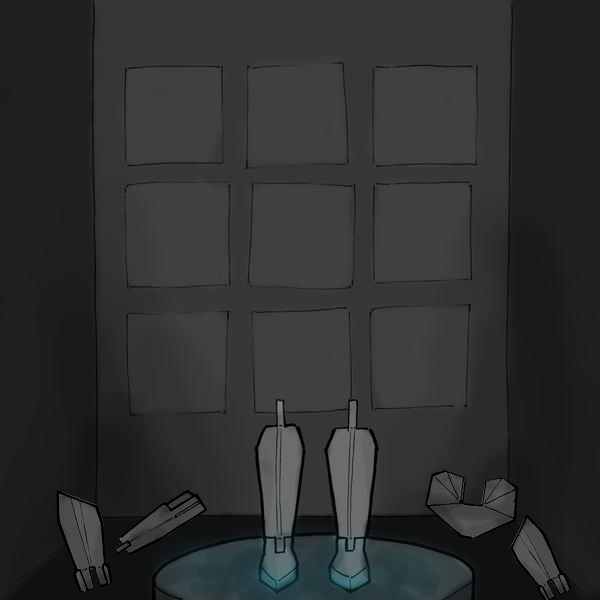

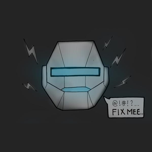
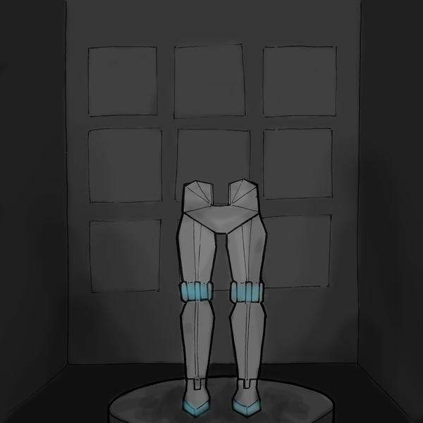
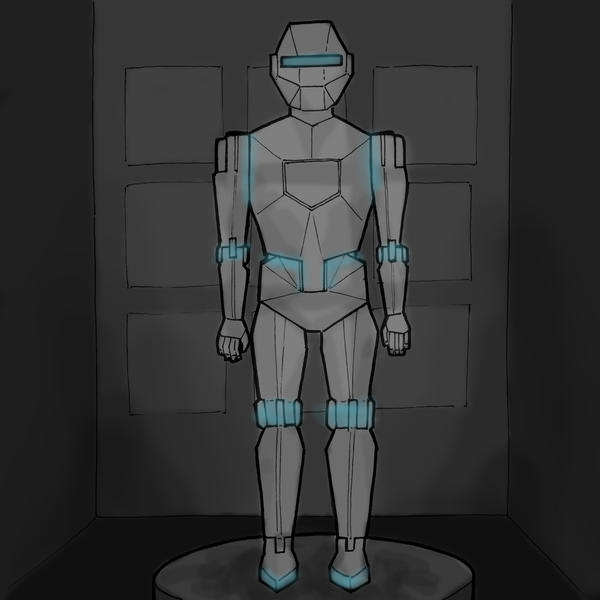
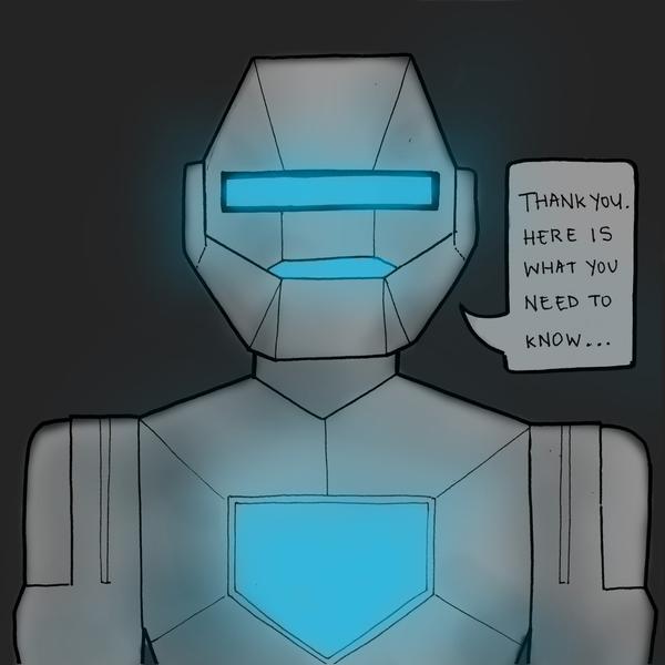
Your team of explorers enters a room to find robot components strewn all over the floor. In the center, a pair of feet are attached to the ground and illuminated. Suddenly, a robot head lights up and starts to talk. He introduces himself as Percy, and pleads for your help to reassemble his body. In return, he promises to help you move on to the next room. As you start to place components in their correct location, joints are illuminated to indicate a good connection. Once you complete the puzzle, Percy is reanimated and tells you what you need to know! On to the next adventure!
Design Intent
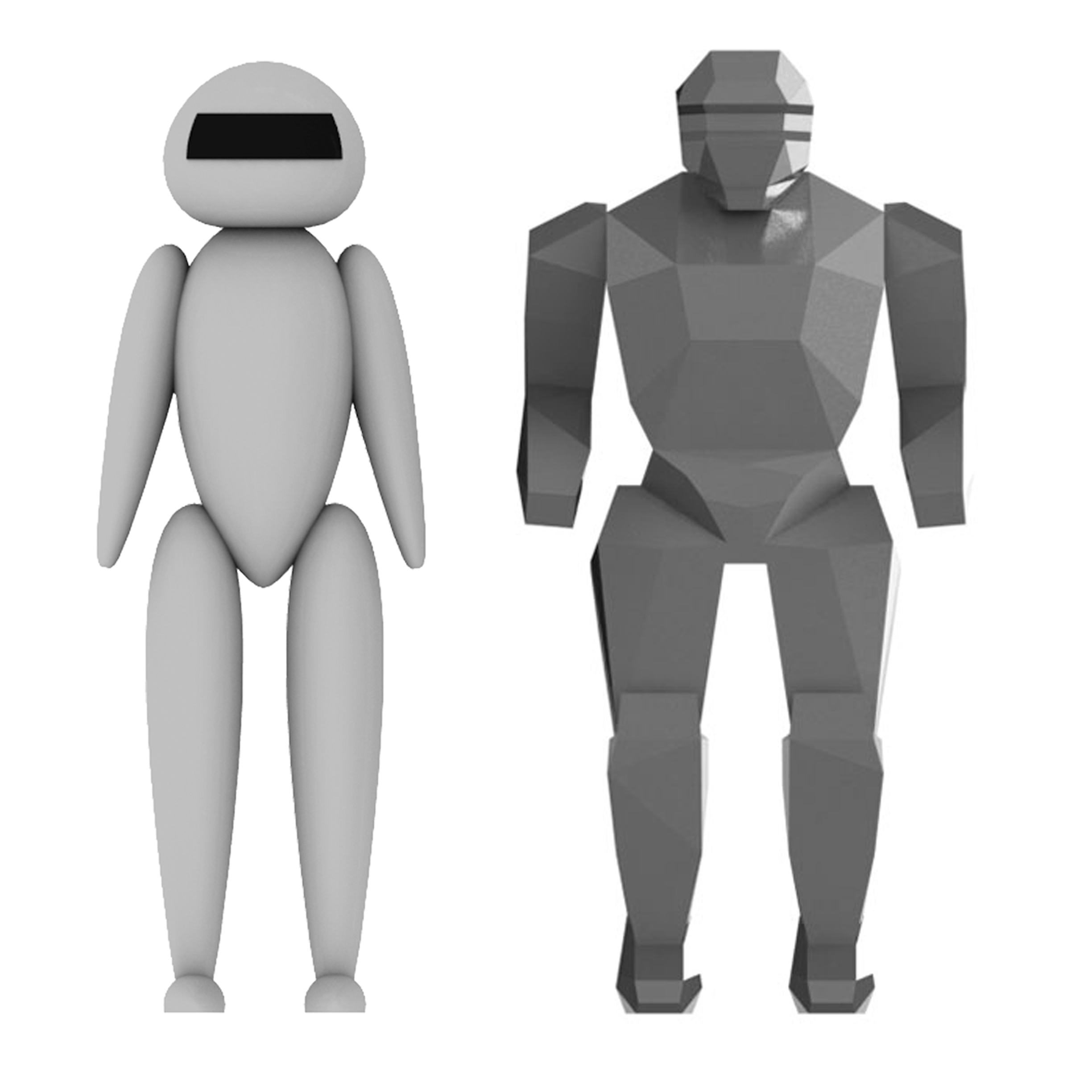
We initially designed Percy in a faceted form, but user feedback indicated that this form seemed agressive and scary, not the emotions we wanted to convey for our robot ally. We developed a second design composed entirely of C2 curvature to communicate friendliness and hi-tech sophistication. We conducted user interviews and found that this new form came across as too friendly and not as a robot that could protect the 5W!TS visitors once it was assembled. From this feedback we decided to continue with the faceted form, but we updated the geometries to be less angular and to communicate a strong and lean body for our robot instead of the bulky and overly muscular original form.

Interaction

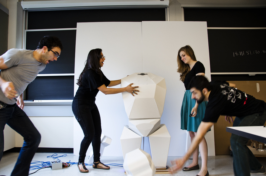
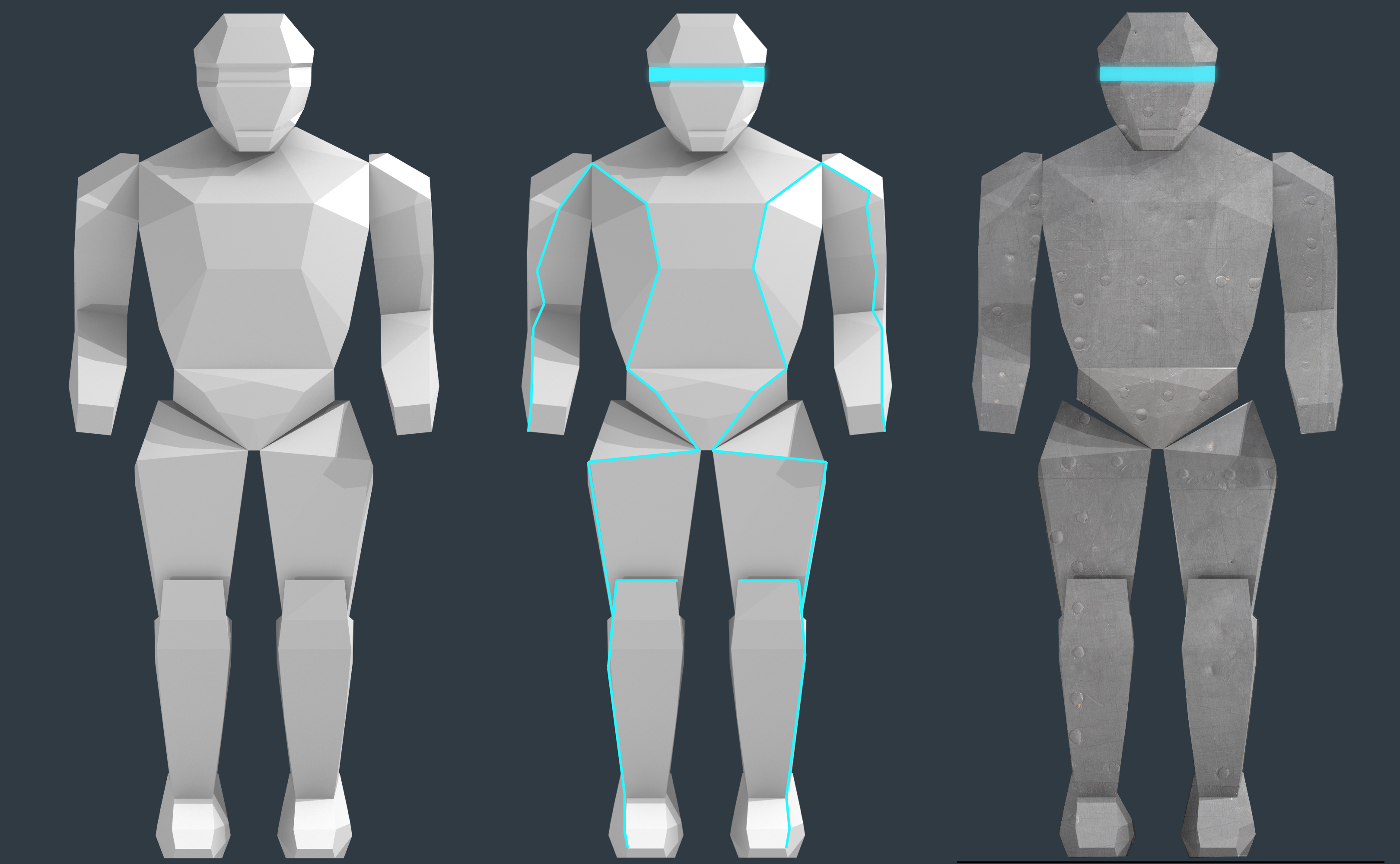
Our robot puzzle can be scaled to be fun and interactive for small to large groups of individuals. We currently split our robot into 9 parts (legs, thighs, pelvis, torso, arms, and head) but it can be separated into more parts so that even in groups of 15 every adventurer would be able to assemble a part.
The puzzle is very interactive and requires teamwork to add each robot part correctly. It will be a great way to encourage collaboration and immerse visitors in the adventure.
Challenge Level
Since the number of robot parts will be set, assembling the robot may be more difficult for smaller or younger groups. To assist in assembly, the robot head can be programmed to give the groups hints at certain time intervals if the robot is still not assembled. For example, with slightly more complicated programming and electronics, two sides of a joint (one side on the partially constructed robot and one on a part on the floor) could start blinking to hint at a correct match.
Resetting
A crucial part of our robot design is the resetting feature, allowing the puzzle to reset for the next group without any outside interference. After a group moves on to the next group, the robot can be programmed so power to the robot shuts off, causing the electromagnets to shut off. The base legs of the robot stand at a slight angle so that without the power of the electromagnets, the entire robot will collapse to the ground.
Click here if the video is not playing properly, or switch to Chrome/Safari.
Fabrication Process
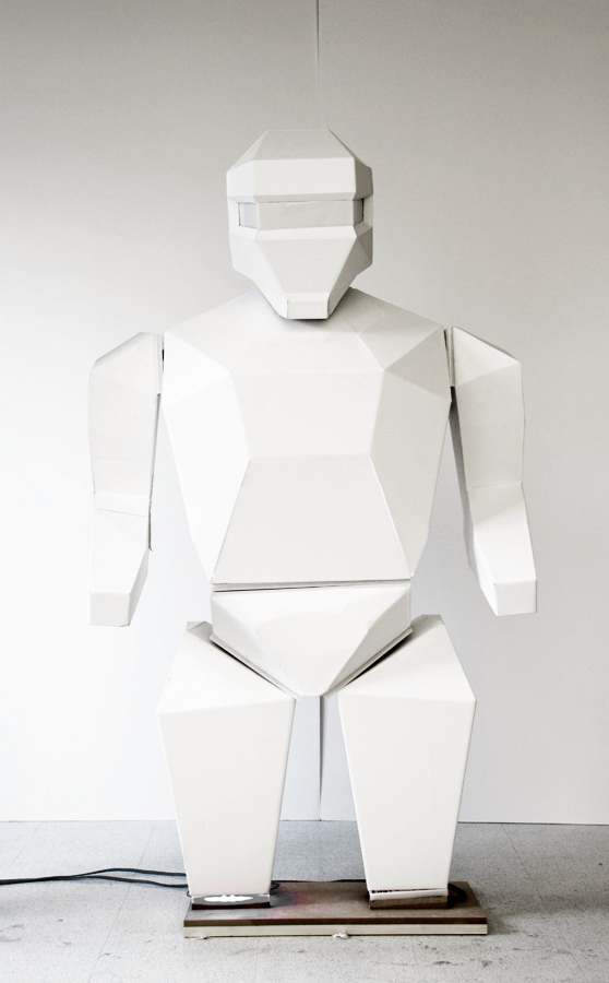
For this prototype, we had budgetary and time constraints that greatly dictated our fabrication and material choices. Each of Percy's parts are constructed with foamcore, and the interal joints consist of electromagnets, steel, and aluminum contacts.

Housing Construction
We converted our 3D CAD model of Percy into a 2D model that we CNC routed out of foamcore. We folded each of these cut foamcore sheets to form each 3D robot part, leaving a flat at each end so that we could insert the joints. Foamcore was chosen as a material because it is cheap, light, and could be folded without breaking under strain.


Joint Manufacturing
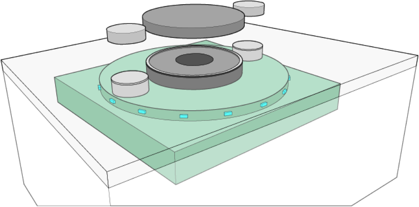
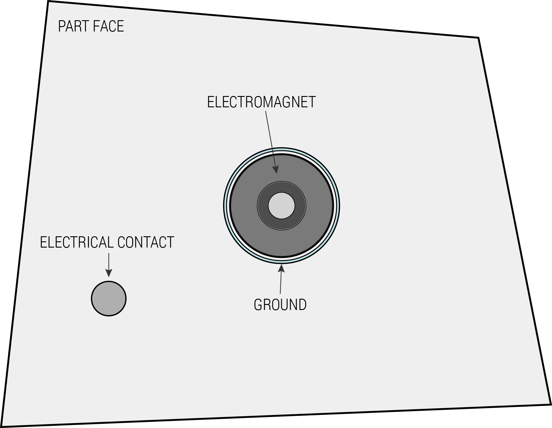
Each joint consists of two sides: one with an electromagnet and an LED strip and an opposing side with a steel plate to interface with the electromagnet. Both sides also have two aluminum contacts for 12V and ground. For the electromagent side, we chose to CNC Mill a RenShape foam base since this material combines strength and durability while remaining lightweight. We inserted the electromagnet, aluminum contacts, and LEDs and wired them through the back of the foam. On top of the green foam we placed a lasercut acrylic layer to hide the electronics beneath while allowing the LED light through. For the opposing side we worked with the foamcore housing of the robot part and attached a steel plate to the top with two aluminum connectors inserted through the foamcore into a layer of green foam for added stability.
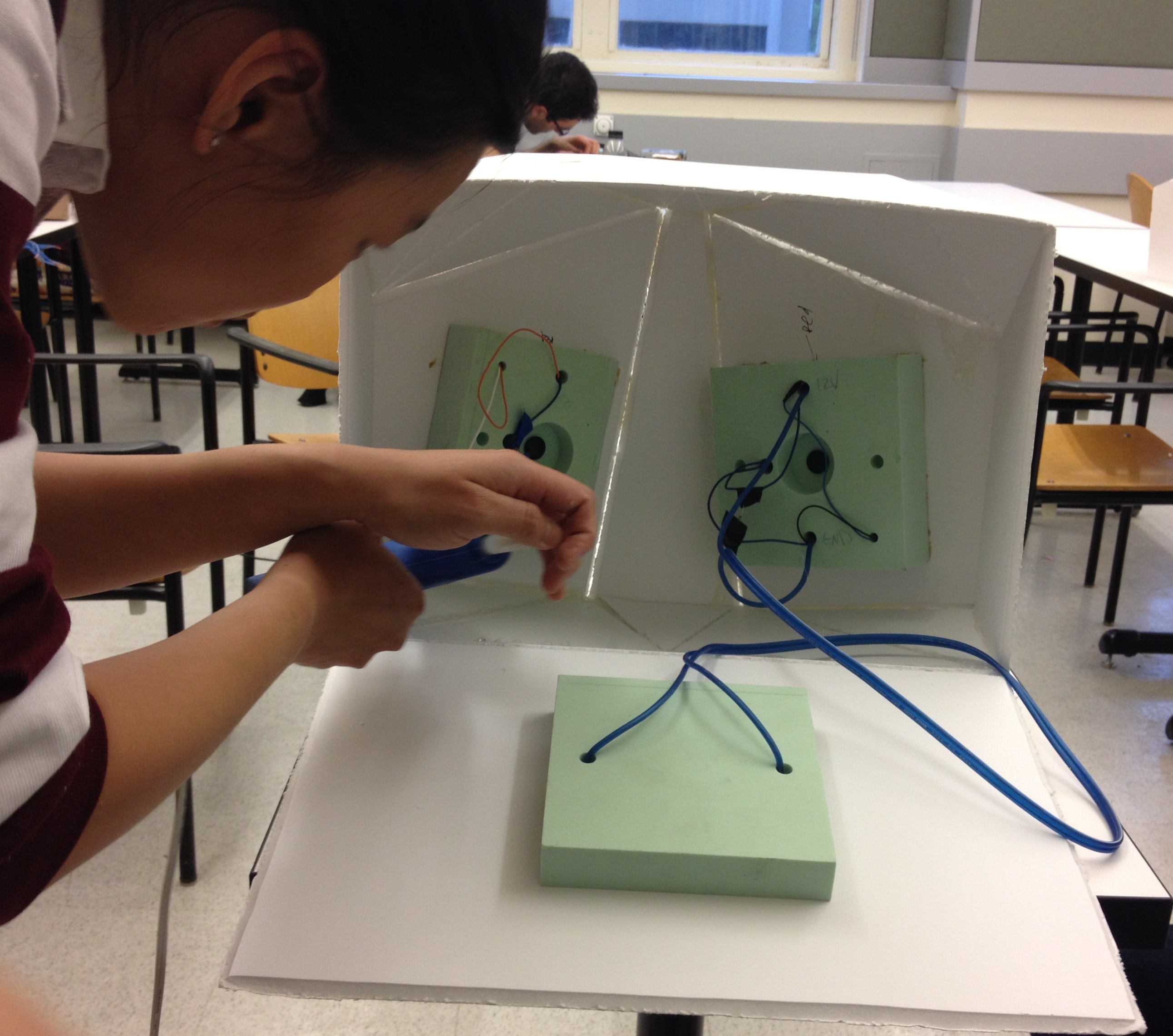
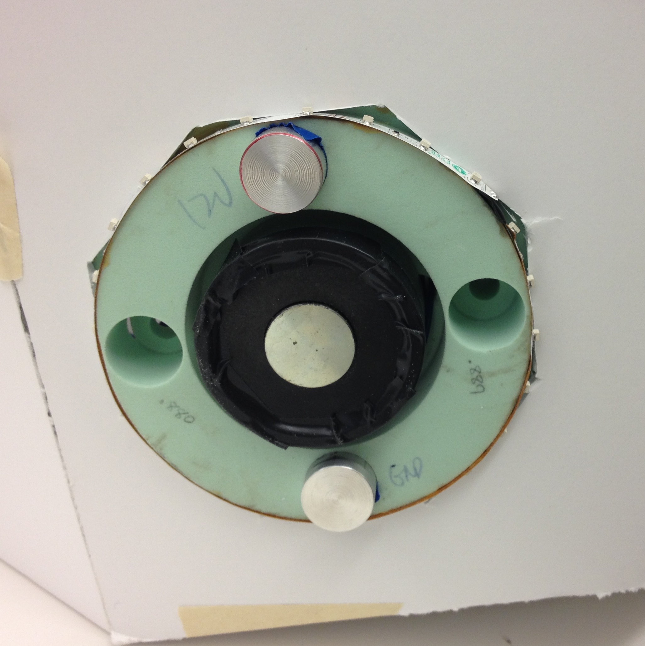
As joints are assembled corrected, the aluminum contacts complete the circuit within that joint. This causes the LEDs to light up, indicating a correct match, and it also activates the electromagnet, holding the joint together. Power is supplied through the fixed robot feet in the floor, and is translated to each robot part as it is added to the robot assembly by 5W!TS visitors. The head is the only part that needs to be powered while it is separated from the robot body, so we installed a battery inside to drive the head LEDs.
Click here if the video is not playing properly, or switch to Chrome/Safari.
Electronic Systems
Our robot's contains three different areas of electronic circuits and control: the power control, joint circuitry, and head electronics. All three components are relatively simple in both hardware and software.
Power Control
In order for Percy to stay put together, his body is powered from the bottom with a standard 12V power supply. This power supply provides power to both the electromagnets in the joints and the LEDs. Since each electromagnet draws half an amp, and each small LED strand in a joint draws roughly 0.1 amps, the total amount of amperage needed is 0.6A per joint. This value increases as you add more LEDs to the joint or increase the strength of the electromagnets.
Reseting Percy is as simple as turning off the power, which essentially boils down to a switch closure. Given how the 5W!TS central control system handles the puzzle, this reseting mechanism is simple. One could also use a circuit with a single transistor switching the power on or off.
Joint Circuitry
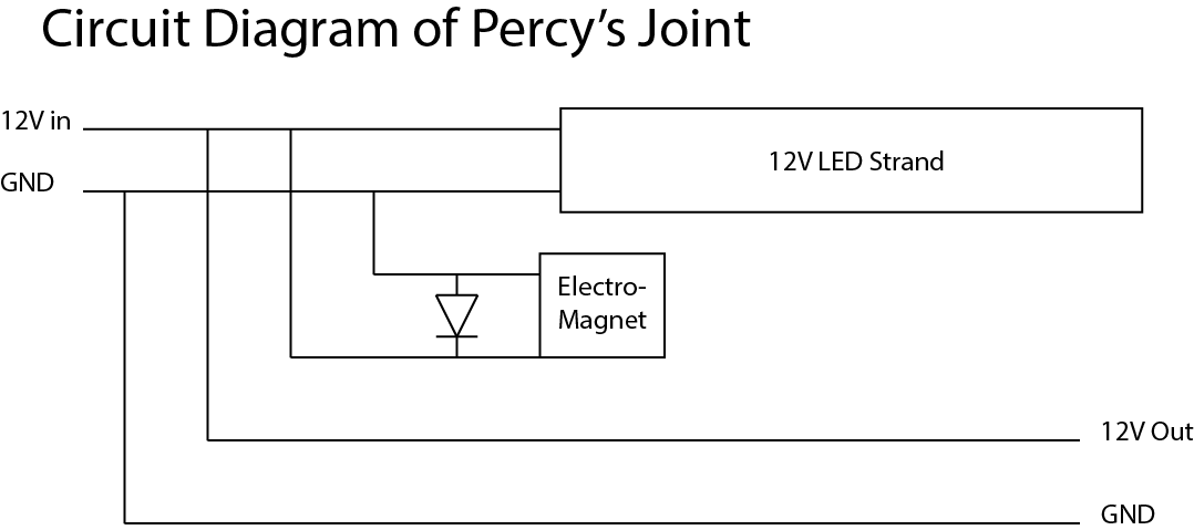
Each joint has two different sides: one with only steel and electrical contacts, and another with an electromagnet, LEDs, and contacts. The steel and contact side provides power to the attaching side containing the electromagnet and LEDs, turning on the LEDs and engaging the electromagnet with the steel. The electromagnet side branches the power in parallel to the small LED strand and the electromagnet. The power also moves up to the next joint in the piece.
One interesting issue we encountered was that the electromagnets created significant back current when powered down. This back current can easily destroy LEDs in the joint or other electrical components in the system. To diffuse this back current, we added a protective diode at the power poles of the electromagnet, as shown in the circuit below.
Head Electronics
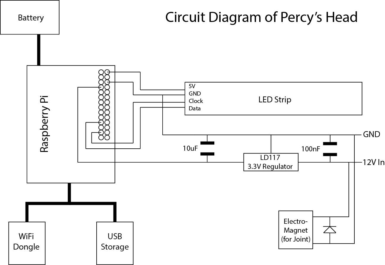
The head operates almost exactly the same as it did in the sketch model and concept refinement phases. The audio is created by passing English phrases to the unofficial Google Translate API set to the Armenian language, speeding it up about 20%, and adding an echo delayed by about one-hundredth of a second. The lights match the audio volume levels at each time step, processed as described in our Concept Refinement phase. The head is signalled from a central server via TCP socket to play a certain track, coordinating the sound played in the room and the lights within the head. The lights are powered by a battery that is effectively just a backup phone battery.
We chose to play the audio over the main room speakers for two reasons. First, the users will be able to hear the audio much better this way, especially since we can't control the orientation of the head and any speakers inside it when users enter. Second, since the head runs on a battery, powering any audio through the head would be very difficult.
The LEDs are controlled using the WS2801 protocol and are connected to a Raspberry Pi controller via the SPI GPIO pins. The LEDs have full 24 bit RGB color available and can achieve an extremely high framerate (over 60 fps), though they are generally limited to roughly 20 fps given the size of the audio time step. An example strand that would work for Percy is this strand on Amazon. Alternatively, if you only wanted one color of light in Percy's head, you could use a single color LED strand and modulate the power using PWM and a power transistor. Scaling the PWM duty cycle with increases in speech volume will produce the same effect.
The Raspberry Pi is powered through a micro-USB port, which is in turn connected to the mobile phone backup battery pack. To power the lights, the battery should provide 2A of current output. One affordable battery providing roughly 15-20 hours of battery life is this one on Amazon.
Aside from the LEDs, the Raspberry Pi has a few extra peripherals attached to it. In our prototype, the Raspberry Pi connected to the main server using WiFi. The Pi also has a small circuit for detecting when the 12V signal has reached the head, meaning that the puzzle is complete. Originally, this circuit was designed a simple voltage divider, but the voltage drop from foot to head made the circuit ineffective. Instead, this circuit should be made using a voltage regulator, as shown in the diagram below. Finally, all the audio and light data is stored on a USB stick attached to the Pi, allowing for script and color changes without any reprogramming.
Finally, below is a video of the head saying all of the currently recorded phrases.
Click here if the video is not playing properly, or switch to Chrome/Safari.
All of the code for both the server and the head are publicly available here on Github.
Future Improvements
After fabricating this preliminary prototype of Percy, we came across several areas for improvement that we would like to tackle in future development.
Visual
The current prototype we created is currently white, which acts as a blank canvas. In the future, different surface treatments can be investigated based on the theme that 5W!TS chooses to employ for their Sci-Fi adventure, as seen below.
Fabrication
For this prototype, we used folded foam core to create Percy’s faceted geometry. Because of this, the pieces were fairly weak and did not stand up well to abuse or drops. Additionally, the imprecision of foam core resulted in inaccurate connections and alignment of joints. For future production, we recommend creating molds and using fiberglass to create the robot components. This will result in much stronger parts with better resolution and smaller tolerances. We would also like to fabricate each component such that it easily opened, in order to allow for access to internal components and circuits.
Joints
One of the issues we encountered with joints was a variation in force between the electromagnets and steel plates. This resulted in some joints that weren’t strong enough to counteract gravity. Additionally, the steel plates were observed to slowly magnetize after prolonged exposure to the electromagnet. To eliminate these issues, a functioning final version of this experience should utilize a control loop using a Hall Effect sensor which measures the intensity of magnetic fields. This sensor could be used to increase the magnetic strength upon initial connection and decrease it once a stable steady-state has been reached. It could even be used to make connecting the joints more difficult, thus adding a way to tune difficulty.
Our initial joint design did not have the spring loaded contacts mentioned in the concept refinement phase because a lack of off-the-shelf parts meant that we were time-constrained. We found that relying on precision component assembly was not very effective and that the added contact made alignment even more difficult. A future iteration of this joint would place a grounded sleeve around the electromagnet and a single contact for the positive rail of the power supply as illustrated in the figure below.
The problem of inaccurate puzzle piece placement could be solved with varying radii of the single contact from the electromagnet. 5WITS! would likely prefer a “smart parts” system. In such a system each puzzle piece would have an embedded microcontroller and correct placement would be communicated through a system like RFID. In this case, parts would need battery packs to function properly. Alternatively, a wireless power system could be implemented through partnerships with companies like WiTricity making the entire system more elegant and simple.
Feedback
To enable decreased supervision from 5W!TS staff and inform users of their progress, additional feedback could be incorporated into the component design. Instead of using the power source in the feet as the sole source of power the entire body, all of the components could be smart (fitted with a battery). This allows Percy to provide clues to players if they are stuck, by blinking LEDs in the two halves of the next joint to be connected. Audio feedback could also be incorporated throughout the assembly process.
Directive Classified: 2.744 Spring 2014
Previous Work for Project
Look 'ma! No hands!
It falls apart!