 |
 |
| HOW AN ELEVATOR WORKS | ||
| QUESTIONS OR COMMENTS | ||
 |
AUTHOR: | Rhonda Salzmon |
| E-MAIL: | rsalzman@mit.edu | |
| COURSE: | 2 | |
| CLASS/YEAR: | 3 | |
MAIN FUNCTIONAL REQUIREMENT: Move people and heavy objects from one location to another higher or lower, location.
DESIGN PARAMETER: An elevator can be used to meet these requirements.
BACKGROUND SECTION:
In order to do this, the elevetor turns electrical power into mechanical (rotational) power. The brake of the elevator must be designed in order to guarantee safety during normal day use. The brake must also be able to engage in extreme cases in which the elevator cable is broken or other unforeseen circumstances arise. In addition, the elevator must pick up and drop off passengers as efficiently as possible. If a collection of elevators is used, a complex controller usually controls them.
The elevator must fit within the given space requirements of the building. It must be made large enough to deal with the normal daily traffic and to move the necessary objects within the building. It cannot be made too large and, therefore, affect the structure of the building itself. Possible restrictions on the weight carried within the elevator may be determined from the size of the motor and the other components within the elevator system. This weight limit must be large enough to handle daily usage.
GEOMETRY/STRUCTURE AND EXPLANATION OF HOW IT WORKS/ IS USED:
Traction Drive/Roping System
A roping system is used to attach the motor/gear reducer, the elevator car and the counter weight. There are many different kinds of arrangements that can be used. In one possible arrangement, such as shown in Figure 2, both ends of the elevator rope are anchored to the overhead beam. Both the elevator car and the counter weight are attached to free moving pulleys. The traction drive is attached to a stationary pulley.
The traction drive is the method of converting the input mechanical power (in this case the turning of a shaft) into useable mechanical power in the system (the vertical movement of the elevator). The friction between the ropes and the sheave grooves, which are cut on the pulley, initiates the traction force between the traction drive and the rope.
When the traction drive is rotated power is transferred from the traction drive to the elevator car and counter weight. Power is only needed to move the unbalanced load between the elevator and the counterweight.
Gears
An elevator's function is to convert the initial electrical power, which runs the motor, into mechanical power, which can be used by the system. The elevator is composed of a motor and, most commonly, a worm gear reducer system. A worm gear system is made up of a worm gear, typically called the worm, and a larger round gear, typically called the worm gear. These two gears which have rotational axes perpendicular to each other, not only decrease the rotational speed of the traction pulley (1), but also change the plane of rotation. By decreasing the rotation speed, with the use of a gear reducer, we are also increasing the output torque, therefore, having the ability to lift larger objects for a given pulley diameter. A worm gear is chosen over other types of gearing possibilities because of its compactness and its ability to withstand higher shock loads. It is also easily attached to the motor shaft, sometimes through use of a coupling. The gear reduction ratios typically vary between 12:1 and 30:1.
The motor component of the elevator machine can be either a DC motor or an AC motor. A DC motor had a good starting torque and ease of speed control. An AC motor is more regularly used because of its ruggedness and simplicity. A motor is chosen depending on design intent for the elevator. Power required to start the car in motion is equal to the power to overcome static, or stationary friction, and to accelerate the mass from rest to full speed. Considerations that must be included in the choice of an acceptable motor are good speed regulation and good starting torque. In addition, heating of various electrical components in continuous service should not be excessive.
Brakes
The most common elevator brake is made up of a compressive spring assembly, brake shoes with linings, and a solenoid assembly. When the solenoid is not energized, the spring forces the brake shoes to grip the brake drum and induce a braking torque. The magnet can exert a horizontal force for the break release. This can be done directly on one of the operating arms or through a linkage system. In either case, the result is the same. The break is pulled away from the shaft and the velocity of the elevator is resumed.
In order to improve the stopping ability, a material with a high coefficient of friction is used within the breaks, such as zinc bonded asbestos. A material with too high a coefficient of friction can result in a jerky motion of the car. This material must be chosen carefully.
Typically the efficiency of the geared machine is 60 percent for the motor and gear box assembly. This efficiency was estimated for a load of 2500lb, which matches a regularly sized residential elevator, being driven at 1.75 m/s.
DOMINANT PHYSICS:
There is a transfer of power throughout the elevator system. Electrical power put into the motor is equal to:
![]() (for
an AC motor)
(for
an AC motor)
Where V is the voltage and I/Ö 2 is the AC current source. This power is then transferred through the output of the motor shaft,
![]() .
.
Where T is the torque and w is the rotational speed. Once the power is transferred through the gear reducer the output speed will be reduced and the torque will be greater. The overall power will be slightly lower as the system is not 100% efficient. Tension on the rope from the elevator pulley is equal to the weight of the elevator, We. The tension on the rope from the counter weight is Wc.
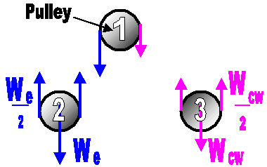 |
| Figure 1. Free body diagram of the pulley system |
The following analysis has been done for steady state (no acceleration )operation. The
force on the driving pulley is equal to the difference of the two exerted tensions on each
side. On one side, this force is equal to We and on the other side, it is Wc.
Therefore, the net force exerted on pulley 1 (the drive
pulley) is:
![]()
In order to find the power required for elevator movement, either the rotational speed
of the drive shaft (attached to pulley 1) or the velocity of the elevator must be known.
The output power is (assumming 100% efficiency),
![]()
where r is the radius of the pulley (pulley 1).
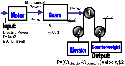 |
| Figure 2. Power flow through a typical elevator |
LIMITING PHYSICS:
As explained above, the brake is held closed by a spring and released using a magnet. The free body diagram below shows how these forces are distributed. The force exerted by the spring is much closer to the pin joint and, therefore, is easily overridden by the force of the magnetic pull because of its longer moment arm (great distance from the point of rotation).
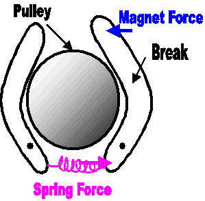 |
| Figure 3. Diagram of the break system |
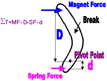 |
| Figure 4. Free body diagram of the break system |
PLOTS/GRAPHS/TABLES:
None Submimtted
WHERE TO FIND ELEVATORS:
Elevators can be found in many residential and business buildings. They are used not only to transport people but also heavy object which would in other cases be difficult to transport.
REFERENCES/MORE INFORMATION:
Lubomir Janovský. Elevator Mechanical Design: principles and concepts.
England: Ellis Horwood Limited, 1987.
George R. Srakosch. The Vertical Transportation Handbook
Third Edition. John Wiley & Sons, Inc., 1998.