 |
|
| HOW A SAIL BOAT SAILS INTO THE WIND | ||
| QUESTIONS OR COMMENTS | ||
 |
AUTHOR: | Robin C. Evans |
| E-MAIL: | rrobin@mit.edu | |
| COURSE: | 2 | |
| CLASS/YEAR: | 4 | |
MAIN FUNCTIONAL REQUIREMENT: Propel a boat with or against the wind
DESIGN PARAMETER: Airfoil (the sail)
A BIT OF HISTORY:
Square Sails 3000 BC - 900 AD |
The first sailboats employed square sails. These boats successfully plied up and down the Nile and across seas for thousands of years, despite the limitations of the configuration. The square sails were pushed by the wind and the boat could only sail windward. All of the forces were in the same direction. |
- Wind Force + Drag Force = Boat Mass * Acceleration.
The wind force overcomes the drag force of the boat.
- Drag Force = Water Pressure * Keel Area + Air Pressure* Exposed
Boat Area
Most of the drag is due to the keel moving through the water. The sails, lines, mast, crew and cargo also add wind resistance.
- Wind Force = Wind Pressure* Sail Area.
The greater the wind pressure and the greater the area of the sail, the greater the wind force.
Lanteen/Triangle Sails 900 AD
 |
Two thousand years ago, triangular sails appeared. With proper orientation, these sails could convert wind power from any direction into forward thrust. The sail might be pushed or pulled by the wind force, and the pull was stronger than the push. Although there was no physical understanding of the pulling force, it allowed the boat to sail into the wind. In the 18th century, the pulling force was identified as LIFT, and it was discovered that it was generated by fluid flow over a curved surface, an AIRFOIL. There are two (often hotly contested) theories to explain the phenomenon of lift over the top of an airfoil: BERNOULLI and EULER. |
DOMINANT PHYSICS:
BERNOULLI'S EQUATION
Edmund Bernoulli theorized in 1738 that under certain conditions, one can the energy in a fluid system is constant.P + 1/
2rV^2 + gh = CP = Fluid Pressure [N/m^2]
r = Fluid Density [kg/m^3]
V = Fluid Velocity [m/s]
g = Gravitational Acceleration Constant [N/m^2]
h = Height [m]
Bernoulli's principle may be applied to when a fluid flows outside the boundary layer. The flow must furthermore be modeled as incompressible, steady, and frictionless.
(Put Bernoulli airfoil picture in here)
Usually, one can assume the gravitational effects are negligible compared to the magnitude of the increase in VELOCITY which results in a DECREASE in PRESSURE. The streamlines separate at the leading edge of the airfoil and meet again at the trailing edge. The pressure above is LOWER than the pressure below, creating a LIFTING FORCE.
The other lift theory for is based on EULER'S EQUATION.
EULER'S EQUATION
dP/dn = rV^2/RP = Fluid Pressure [N/m^2][psi]
n = Normal Vector to Curved Streamline
r = Fluid Density [kg/m^3]
V = Fluid Velocity [m/s]
R = Radius of Curvature of Streamline [m]
The air pressure above the airfoil along a NORMAL VECTOR from the wing surface is inversely proportional to the distance from the RADIUS OF CURVATURE. At a certain distance above the airfoil is AMBIENT air pressure. The pressure INCREASES from the center of curvature along the normal vector until it reaches ambient pressure. The air pressure closer to the airfoil thus must be LOWER than the ambient pressure. Again, the pressure above is lower than the pressure below and a LIFTING FORCE is created.
For more on airfoils and lift, see How An Airfoil Works by Mealani Nakamura and How Hydrofoils Work by Tina Rosado.
HOW DOES LIFT SAILBOATS USE LIFT?
When the boat sails "into the wind", the bow is pointed into the APPARENT WIND, which is the vector resolution of the TRUE WIND and the BOAT COURSE.The SAIL in the wind acts as an AIRFOIL and the HULL in the water acts as a HYDROFOIL, so there are two sets of forces acting on a sailboat: AERODYNAMIC and HYDRODYNAMIC
AERODYNAMIC FORCES
(insert aerodyn forces )
There are two ways to examine the aerodynamic forces acting on the boat.
1. Sailors look at the forces that control the BOAT'S BEHAVIOR:
- The DRIVING FORCE is the thrust that moves the boat along its course.
- The HEELING FORCE is perpendicular to the course. It spills wind, decreases speed, and tips the boat.
The goal is to maximize the driving force. However, as the driving force increases, so does the heeling force. The sailor makes a compromise between speed and stability.
2. An alternate vetor resolution is used to analyze the sail efficiency.
- The low pressure over the curved sail creates a crosswind LIFT force.
- Viscous and pressure effects result in DRAG opposite the motion of the boat
- The LIFT and DRAG may be resolved into a TOTAL AERODYNAMIC FORCE (AF).
- The angle ea between the LIFT and the AF is the AERODYNAMIC EFFICIENCY, a measure of speed.
Cot ea = L/D.
HYDRODYNAMIC FORCES
- The curved surface of the hull creates a HYDRODYNAMIC SIDE FORCE (SF), which balances the aerodynamic HEELING FORCE.
- The water pressure over the cross-sectional area of the keel creates a RESISTANCE (R).
A large SF increases STABILITY, but is proportional to the resistance, which reduces SPEED.
- These two may be resolved into a TOTAL HYDRODYNAMIC FORCE (HF).
- The angle eh between the SF and HF is the HYDRODYNAMIC EFFICIENCY, a measure of stability.
Cot
ea = SF/RHOW DO SAILORS MAXIMIZE BOAT EFFICIENCY?
The angle between the boat course and the apparent wind direction, b, is the boat's ANGLE OF ATTACK.
b
= ea + eh.The angle between the sail CHORD LINE and the wind direction, a is the sail's ANGLE OF ATTACK. If the sail points straight into the wind, there will be no airfoil shape, and no lift. The sail must be slightly angled The largest speeds are obtained while sailing as close to the wind as possible, while the sail chord is approximately co-linear with the boat's centerline. The sailor must turn the boat to follow the course, but alters the sail position (lets the sail out) to maintain the sail's optimum angle of attack.
 |
 |
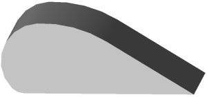 |
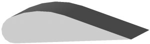
| Slim Airfoil | "Normal Airfoil" | "Thick" Airfoil |
The sailor may also change the sail's shape for changing wind speeds.
A thick airfoil generates more lift, but also more drag. If you subscribe to Bernoulli's theory, the increases are due to the higher velocity and lower pressure. If you prefer Euler, the lower pressure is due to the smaller radius of curvature . For the same reasons, a thin airfoil generates less drag, but also less lift.
The sail is "kept tight" in the shape of the thin airfoil at moderate to high wind velocities. Large lift is coupled with large heeling and the boat may tip over. When the wind speed is low, the sail is "let out" a bit to generate more lift, and thus more driving force. However, if the sail is let out too much, it will luff and force the boat away from the wind.
LIMITING PHYSICS:
None Submitted
PLOTS/GRAPHS/TABLES:
None Submitted
WHERE TO FIND SAIL BOAT:
On the water!
REFERENCES/MORE INFORMATION:
Airfoil and Hydrofoils
Marchaj, C.A. Aero-Hydrodynamics of Sailing. Dodd, Mead & Company, 1979.
Evans, Michael E. MSME. Email from January 13, 1998.
Perdichizi, Richard. Senior Technical Instructor, Massachusetts Institute of Technology Aerodynamics and Astronomics Department. Conversation on January 14, 1998.