 |
 |
| DIGITAL SCANNER | ||
| QUESTIONS OR COMMENTS | ||
 |
AUTHOR: | Jennifer Blundo |
| E-MAIL: | jblundo@mit.edu | |
| COURSE: | 2 | |
| CLASS/YEAR: | 1 | |
MAIN FUNCTIONAL REQUIREMENT: Convert an image/photo from analog to digital format.
DESIGN PARAMETER: Digital Scanner
GEOMETRY/STRUCTURE:
| Item | Purpose | |
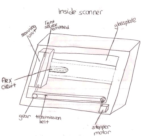
| 1. | Stepper Motor | Powers the transmission belt |
| 2. | Logic Board | Relays information to and from the scanner and the computer |
| 3. | Scanning Unit/Carriage | Contains a light source and CCD sensors |
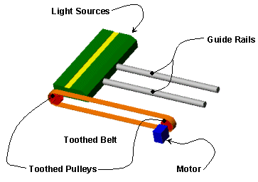
| 4. | Transmission Belt | Moves the scanning unit across the image |
| 5. | Flex Circuit | Carries the CCD information to the logic board |
| 6. | CCD sensors | Converts measured reflected light into a voltage proportional to the light intensity |
| 7. | Glass Plate | Allows light to pass from light below glass to image and supports image |
| 8. | ADC | Analog digital converter unit that changes CCD measured voltage to digital |
 |
 View as VRML |
| Sketch of Main Scanner Components | Mechanism For Moving Light Source In Scanner |
EXPLANATION OF HOW IT WORKS/ IS USED:
- The image to be scanned is placed on top of the scanner’s glass plate
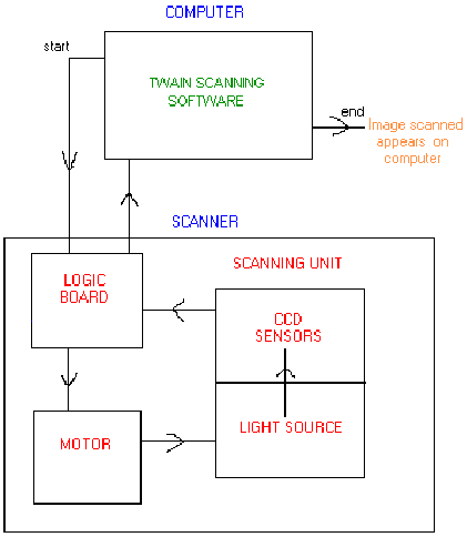
- The computer sends instructions to the logic board about how far the motor is to run and how fast
- The logic board instructions place the scanning unit into an appropriate position to begin scanning
- The scanning unit moves across the image to be scanned at a speed designated by the logic board instruction
- As the scanning unit moves across the image, a light source shines on the image
- The light strikes the image, reflects, and is then reflected by a series of mirrors to the scanner lens
- The light passes through the scanner lens and reaches the CCD sensors
- CCD sensors measure the amount of light reflected through the image and converts the light to an analog voltage
- The analog voltage is changed to digital values by an ADC – analog to digital converter
- The digital signals from the CCDs are sent to the logic board and transmitted back to the computer
The information is stored in the computer as an electronic file made up of pixels. The group of pixels is changed into a picture by the TWAIN scanning software.

A Flow Chart of How a Scanner Works
A Color Scanner vs. a Black/White Scanner
- Black/white scanners only have one light source, and color scanners have three light sources, one for each primary color—red, green, blue.
- Color scanning can be achieved by a one-pass scanner or a three-pass scanner.
- A one-pass scanner scans the image once and records all three colors at the same time, while a three-pass scanner makes three passes over the image and records only one color each pass.
DOMINANT PHYSICS (drive system):
| Variable | Description | Metric Units | English Units |
| Pin | Power input to electric motor | Watts | Horsepower |
| Pout | Power output from shaft | Watts | Horsepower |
| w | Shaft rotation speed | rad/s | RPM |
| hm | Mechanical efficiency | --- | --- |
The scanning unit uses reflection to pass light from the image to the CCD sensors.
The velocity of the shaft connected to the motor can be determined. The power in and the power out of the motor can be calculated:
Pin = I x V (DC motor)
Pout = T x w
hm = efficiency = Pout / Pin
Pin = Pout / hm
The efficiency of these types of motors is about 90%
LIMITING PHYSICS (drive system):
None submitted
PLOTS/GRAPHS/TABLES:
None submitted
APPLICATION OF SCANNERS:
- Compact document scanners, hand held scanners, photo scanners, flatbed scanners, and drum scanners
- CCD sensors are also found in video and digital cameras
REFERENCES/MORE INFORMATION:
Scanning Information Center: Glossary of Scanning Terms
http://www.coe.uh.edu/course/cuin/7317/scanning/glossary.html
Optical Scanner—Encarta‚ Concise Encyclopedia Article
http://encarta.msm.com/index/conciseindex/63/063aa000.html
Scanning Information Center: How does a Scanner Work?
http://www.coe.uh.edu/course/cuin/7317/scanning/work/html
Scanners
http://www.dircon.co.uk/pctechguide/images/18scanners.html
Sylvain’s Home page: CCD
http://www.multimania.com/srondeau.ccd.html