 |
|
| TORQUE CONVERTER | ||
| QUESTIONS OR COMMENTS | ||
 |
AUTHOR: | Manuel Martinez |
| E-MAIL: | manny316@mit.edu | |
| COURSE: | 2 | |
| CLASS/YEAR: | 2 | |
MAIN FUNCTIONAL REQUIREMENT: Transmit "rotational power" using fluid coupling rather than a mechanical clutch.
DESIGN PARAMETER: Hydrodynamic Drive (torque converter) - transmits power via re-circulating fluid in a closed housing.
GEOMETRY/STRUCTURE:
  |
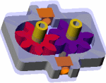
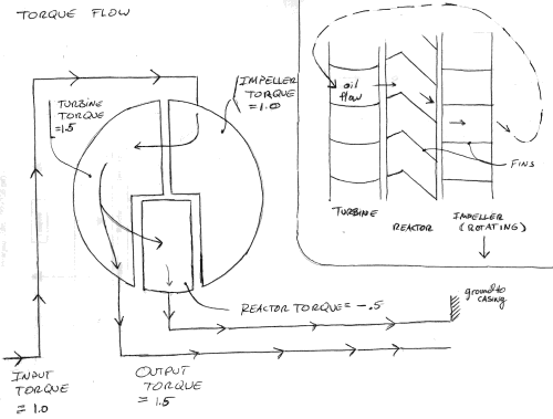
| Detail of Torque Converter Components |
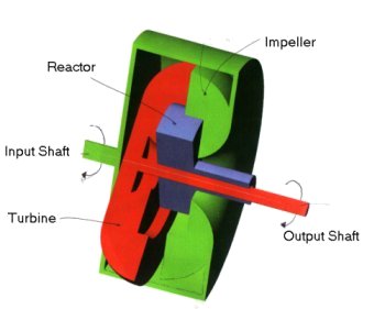
- The impeller is connected to the input shaft.
- The turbine is connected to the output shaft.
- The reactor is "grounded" (meaning rigidly connected) to the casing by means of a one-way clutch.
 |
| Detail of Torque Converter Components |
EXPLANATION OF HOW IT WORKS/ IS USED:
 |
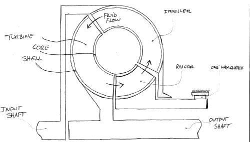
| Detail of Torque Converter Components |
- Power is applied to the input shaft, and in turn, the impeller.
- The torque and angular velocity of the impeller sets the fluid in circular motion throughout the shell.
- Circulating fluid applies a force on the turbine fins.
- When the impeller speed is much greater than the turbine speed, the reactor is grounded to the outside housing. Because it has angled fins, the reactor experiences a torque in the opposite direction as the impeller and turbine.
- This reaction torque causes the turbine to experience an increased torque (see below).
- As the turbine approaches the speed of the impeller, the one way clutch gradually
disengages. The reactor no longer applies a torque to the turbine, so the impeller and
turbine torques become equal in magnitude (see below).

Torque Magnitudes (impeller speed ~ turbine speed)
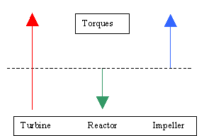 |
| Torque Magnitudes (impeller speed >> turbine speed) |
DOMINANT PHYSICS:
| Variable | Description | Metric Units | English Units |
| P(in) | Power applied to input shaft | Watts | Horsepower |
| P(out) | Power applied to the output shaft | Watts | Horsepower |
| P(loss) | Power loss (coulomb friction and viscous dissipation) | Watts | Horsepower |
| w(in) | Rotational speed of the input shaft | Rad/s | RPM |
| w(out) | Rotational speed of the output shaft | Rad/s | RPM |
| T(in) | Input torque | Newton-meters | ft-lbs |
| T(out) | Output torque | Newton-meters | ft-lbs |
| h (m) | Mechanical Efficiency | --- | -- |
The torque converter receives power from the engine.
P(in) = T(in) * w(in)
A portion of the input power is dissipated in the transmission fluid inside the chamber. The calculations for the power loss are beyond the scope of this explanation and will be referenced as P(loss).
P(loss) = f(friction, viscous effects, other effects….)
P(out) = T(out) * w(out) = P(in) – P(loss) = T(in) * w(in) – P(loss)
…which can also be described in terms of efficiency …
P(out) = h (m) * P(in)
LIMITING PHYSICS:
Efficiency
h (
m) = is P(out)/P(in). This is a function of fluid viscosity, fin design in the turbine and impeller units, T(out), T(in) and other variables. Torque converters run at efficiencies anywhere from 0-95% depending on w(in), w(out), and T(in) and T(out). For example, when a car is stopped at a traffic light, the engine still applies power to the input shaft, but the brakes and transmission prevent the output shaft from rotating. Since P(out) = T(out) * w(out), and w(out) equals zero, P(out) equals zero. Therefore, the efficiency equals zero.When a car is traveling at highway speeds, the turbine is rotating nearly as fast as the impeller. Recalling that they are attached to the output shaft and the input shaft respectfully, then P(in) » P(out) and therefore efficiency is rather high.
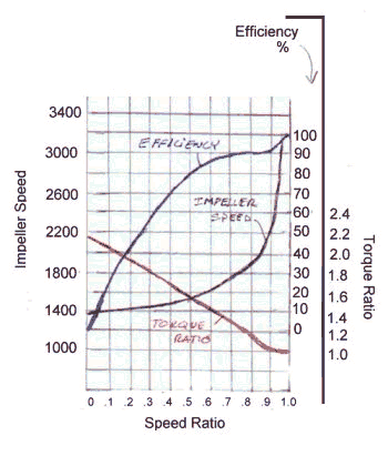
PLOTS/GRAPHS/TABLES:
Graph Variables: Torque Ratio = T(out)/T(in) Speed Ratio = w(out)/w(in) Efficiency = P(out)/P(in) |
 |
WHERE YOU CAN FIND TORQUE CONVERTERS:
A torque converter is found directly between the engine and the transmission gear housings on cars and trucks with automatic transmission. The significance of the torque converter is that it allows the output shaft to be stopped with out stalling the engine, and without physically disconnecting the input and output shafts.
REFERENCES/MORE INFORMATION: