


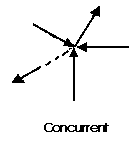
A concurrent coplanar force system is a system of two or more forces whose lines of action ALL intersect at a common point. However, all of the individual vectors might not acutally be in contact with the common point. These are the most simple force systems to resolve with any one of many graphical or algebraic options.
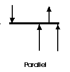
A parallel coplanar force system consists of two or more forces whose lines of action are ALL parallel. This is commonly the situation when simple beams are analyzed under gravity loads. These can be solved graphically, but are combined most easily using algebraic methods.

The last illustration is of a non-concurrent and non-parallel system. This consists of a number of vectors that do not meet at a single point and none of them are parallel. These systems are essentially a jumble of forces and take considerable care to resolve.
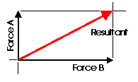 Almost any system of known forces can be resolved into a single force called a resultant force or simply a Resultant. The resultant is a representative force which has the same effect on the body as the group of forces it replaces. (A couple is an exception to this) It, as one single force, can represent any number of forces and is very useful when resolving multiple groups of forces. One can progressively resolve pairs or small groups of forces into resultants. Then another resultant of the resultants can be found and so on until all of the forces have been combined into one force. This is one way to save time with the tedious "bookkeeping" involved with a large number of individual forces. Resultants can be determined both graphically and algebraically. The graphical methods that will be discussed in Lecture 8 are the Parallelogram Method and the Triangle Method. It is important to note that for any given system of forces, there is only one resultant.

It is often convenient to decompose a single force into two distinct forces. These forces, when acting together, have the same external effect on a body as the original force. They are known as components. Finding the components of a force can be viewed as the converse of finding a resultant. There are an infinate number of components to any single force. And, the correct choice of the pair to represent a force depends upon the most convenient geometry. For simplicity, the most convenient is often the coordinate axis of a structure.
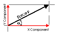 This diagram illustrates a pair of components that correspond with the X and Y axis. These are known as the rectangular components of a force. Rectangular components can be thought of as the two sides of a right angle which are at ninety degrees to each other. The resultant of these components is the hypotenuse of the triangle. The rectangular components for any force can be found with trigonometrical relationships: Fx = F cos theta, Fy = F sin theta (where theta is the angle). There are a few geometric relationships that seem common in general building practice in North America. These relationships relate to roof pitches, stair pitches, and common slopes or relationships between truss members. Some of these are triangles with sides of ratios of 3-4-5, 1-2-sqrt3, 1-1-sqrt2, 5-12-13 or 8-15-17. Commiting the first three to memory will simplify the determination of vector magnitudes when resolving more difficult problems.
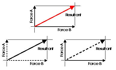
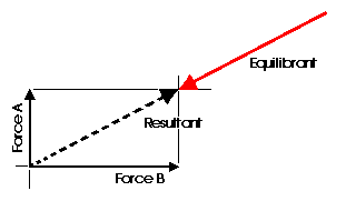
Any concurrent set of forces, not in equilibrium, can be put into a state of equilibrium by a single force. This force is called the Equilibrant. It is equal in magnitude, opposite in sense and co-linear with the resultant. When this force is added to the force system, the sum of all of the forces is equal to zero. A non-concurrent or a parallel force system can actually be in equilibrium with respect to all of the forces, but not be in equilibrium with respect to moments.
Graphic Statics and graphical methods of force resolution were developed before the turn of the century by Karl Culmann. They were the only methods of structural analysis for many years. These methods can help to develop an intuitive understanding of the action of the forces. Today, the Algebraic Method is considered to be more applicable to structural design. Despite this, graphical methods are a very easy way to get a quick answer for a structural design problem and can aid in the determination of structural form.
The following is an example of how an understanding of structural action and force resolution can aid in the interpretation of structural form. The illustration on the left is the Saltash Bridge, design and built by the Engineer Brunel in 1859. Notice the form of the structural elements. The illustration on the right is a retouched imaged to bring the bridge to a state which is akin to a pure suspension bridge. However, there are problems with this design.......
.gif)
.gif)
The suspension chain is loaded with a vertical load as the deck is loaded with a train. This would tend to cause the chain to pull the towers towards the middle of the river. This can be clearly seen if one resolves the tension force into its two orthagonal components. The system is not in equilibrium.
.gif)
.gif)
The system is usually put back into equilibrium by the additional tension force of a chain, or cable, continuing over the support to an anchor on the side of the river. This was not possible here.
.gif)
.gif)
Thus, instead of a tensile force, Brunel replaced this with a compressive thrust from the massive arch. In the illustration below this is seen as the large black arrow. The chain link suspension system works in harmony with the arch....
.gif)
An examination of the resolution of the forces at the support MUST reveal that the resultant passes through the stone pillar.....which it does.
.gif)
.gif)
![]() Components of Forces and Equilibrium
Components of Forces and Equilibrium