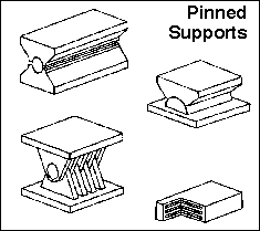
Support and Connection Types
Structural systems transfer their loading through a series of elements to the ground. This is accomplished by designing the joining of the elements at their intersections. Each connection is designed so that it can transfer, or support, a specific type of load or loading condition. In order to be able to analyze a structure, it is first necessary to be clear about the forces that can be resisted, and transfered, at each level of support throughout the structure. The actual behaviour of a support or connection can be quite complicated. So much so, that if all of the various conditions were considered, the design of each support would be a terribly lengthy process. And yet, the conditions at each of the supports greatly influence the behaviour of the elements which make up each structural system.
Structural steel systems have either welded or bolted connections. Precast reinforced concrete systems can be mechanically connected in many ways, while cast-in-place systems normally have monolithic connections. Timber systems are connected by nails, bolts, glue or by engineered connectors. No matter the material, the connection must be designed to have a specific rigidity. Rigid, stiff or fixed connections lie at one extreme limit of this spectrum and hinged or pinned connections bound the other. The stiff connection maintins the relative angle between the connected members while the hinged connection allows a relative rotation. There are also connections in steel and reinforced concrete structural systems in which a partial rigidity is a desired design feature.
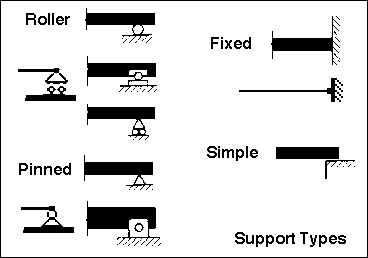
SUPPORT TYPES
The three common types of connections which join a built structure to its
foundation are; roller, pinned and fixed. A fourth
type, not often found in building structures, is known as a simple
support. This is often idealized as a frictionless surface). All of these
supports can be located anywhere along a structural element. They are found
at the ends, at midpoints, or at any other intermediate points. The type
of support connection determines the type of load that the support can resist.
The support type also has a great effect on the load bearing capacity of
each element, and therefore the system.
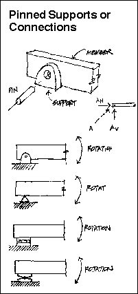
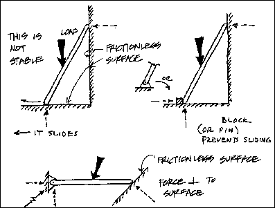
The diagram illustrates the various ways in which each type of support is represented. A single unified graphical method to represent each of these support types does not exist. Chances are that one of these representations will be similar to local common practice. However, no matter what the representation, the forces that the type can resist is indeed standardized.
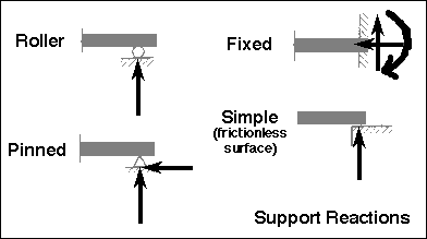
REACTIONS
It is usually necessary to idealize the behaviour of a support in order
to facilitate an analysis. An approach is taken that is similar to the massless,
frictionless pulley in a physics homework problem. Even though these pulleys
do not exist, they are useful to enable learning about certain issues. Thus,
friction and mass are often ignored in the consideration of the behavior
of a connection or support. It is important to realize that all of the graphical
representations of supports are idealizations of an actual physical connection.
Effort should be made to search out and compare the reality with the grpahical
and/or numerical model. It is often very easy to forget that the assumed idealization can be strikingly different
than reality!
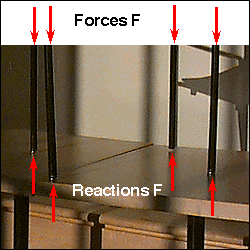
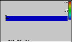
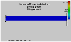
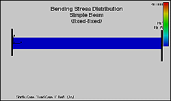
The diagram to the right indicates the forces and/or moments which are "available" or active at each type of support. It is expected that these representative forces and moments, if properly calculated, will bring about equilibrium in each structural element.
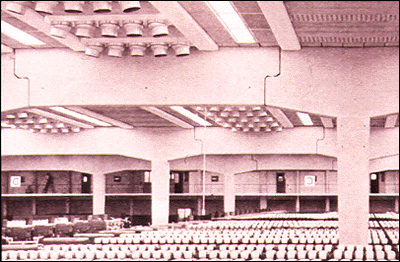
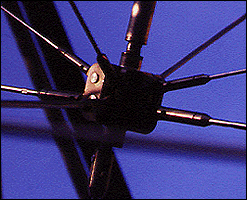
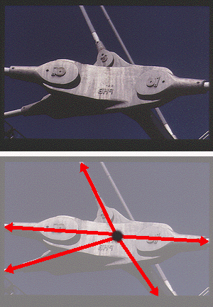
There is an illustration of one of the elements at the Olympic Stadium
in Munich below. It is a cast steel connector that acts as a node to resolve
a number of tensile forces. Upon closer examination one can notice that
the connection is made of a number of parts. Each cable is connected to
the node by an end "bracket" which is connected to a large pin.
This is quite literally a "pinned connection." Due to the nature
of the geometry of the bracket and pin, a certain amount of rotational movement
would be permitted around the axis of each pin.
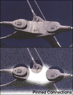
One of the connections from the pyramid of I.M. Pei's Loiuvre addition follows
below. Notice how it too utilized pinned connections.
Pinned connections are confronted daily. Every time a hinged door is pushed open a pinned connection has allowed rotation around a distinct axis; and prevented translation in two. The door hinge prevents vertical and horizontal translation. As a matter of fact, if a sufficient moment is not generated to create rotation the door will not move at all.
Have you ever calculated how much moment is required to open a specific
door? Why is one door easier to open than the another?
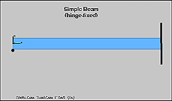
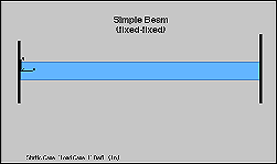
FIXED SUPPORTS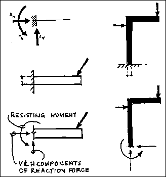
Fixed supports can resist vertical and horizontal forces as well as a moment.
Since they restrain both rotation and translation, they are also known as
rigid supports. This means that a structure only needs one fixed support
in order to be stable. All three equations of equilibrium can be satisfied.
A flagpole set into a concrete base is a good example of this kind of support.
The representation of fixed supports always includes two forces (horizontal
and vertical) and a moment.
FIXED CONNECTIONS
Fixed connections are very common. Steel structures of many sizes are composed
of elements which are welded together. A cast-in-place concrete structure
is automatically monolithic and it becomes a series of rigid connections
with the proper placement of the reinforcing steel. Fixed connections demand
greater attention during construction and are often the source of building
failures.
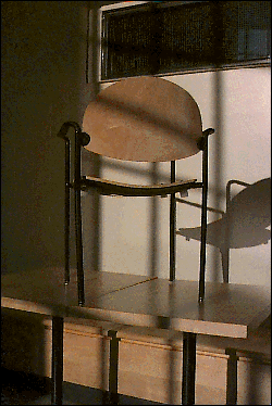
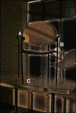
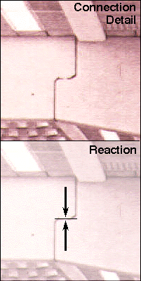
Let this small chair illustrate the way in which two types of "fixed" connections can be generated. One is welded and the other is comprised to two screws. Both are considered to be fixed connections due to the fact that both of them can resist vertical and lateral loads as well as develop a resistance to moment. Thus, it it found that not all fixed connections must be welded or monolithic in nature. Let the hinges at locations A and B be examined in closer detail.
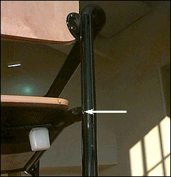
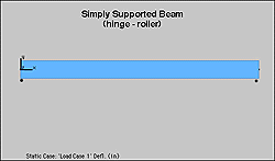
 SIMPLE SUPPORTS
Simple supports are idealized by some to be frictionless surface supports.
This is correct in as much as the resulting reaction is always a single
force that is perpendicular to, and away from, the surface. However, are
also similar to roller supports in this. They are dissimilar in that a simple
support cannot resist lateral loads of any magnitude. The built reality
often depends upon gravity and friction to develop a minimal amount of frictional
resistance to moderate lateral loading. For example, if a plank is laid
across gap to provide a bridge, it is assumed that the plank will remain
in its place. It will do so until a foot kicks it or moves it. At that moment
the plank will move because the simple connection cannot develop any resistance
to the lateral loal. A simple support can be found as a type of support
for long bridges or roof span. Simple supports are often found in zones
of frequent seismic activity.
hmmm.....
TBA