
1.5
Charge Conservation in Integral Form
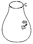
Embedded in the laws of Gauss and Ampère is a relationship that must exist between the charge and current densities. To see this, first apply Ampère's law to a closed surface, such as sketched in Fig. 1.5.1. If the contour C is regarded as the"drawstring" and S as the "bag," then this limit is one in which the "string" is drawn tight so that the contour shrinks to zero. Thus, the open surface integrals of (1.4.1) become closed, while the contour integral vanishes.
But now, in view of Gauss' law, the surface integral of the electric displacement can be replaced by the total charge enclosed. That is, (1.3.1) is used to write (1) as
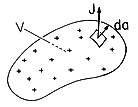
This is the law of conservation of charge. If there is a net current out of the volume shown in Fig. 1.5.2, (2) requires that the net charge enclosed be decreasing with time.
Figure 1.5.1. Contour C enclosing an open surface can be thought of as the drawstring of a bag that can be closed to create a closed surface. Figure 1.5.2. Current density leaves a volume V and hence the net charge must decrease. Charge conservation, as expressed by (2), was a compelling reason for Maxwell to add the electric displacement term to Ampère's law. Without the displacement current density, Ampère's law would be inconsistent with charge conservation. That is, if the second term in (1) would be absent, then so would the second term in (2). If the displacement current term is dropped in Ampère's law, then net current cannot enter, or leave, a volume.
The conservation of charge is consistent with the intuitive picture of the relationship between charge and current developed in Example 1.2.1.
Example 1.5.1. Continuity of Convection Current
The steady state current of electrons accelerated through vacuum by a uniform electric field is described in Example 1.2.1 by assuming that in any plane x = constant the current density is the same. That this must be true is now seen formally by applying the charge conservation integral theorem to the volume shown in Fig. 1.5.3.
Figure 1.5.3. In steady state, charge conservation requires that the current density entering through the x = 0 plane be the same as that leaving through the plane at x = x.
Here the lower surface is in the injection plane x = 0, where the current density is known to be Jo. The upper surface is at the arbitrary level denoted by x. Because the steady state prevails, the time derivative in (2) is zero. The remaining surface integral has contributions only from the top and bottom surfaces. Evaluation of these, with the recognition that the area element on the top surface is (ix dydz) while it is (-ix dydz) on the bottom surface, makes it clear that
This same relation was used in Example 1.2.1, (1.2.4), as the basis for converting from a particle point of view to the one used here, where (x, y, z) are independent of t.
Example 1.5.2. Current Density and Time-Varying Charge
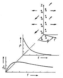
With the charge density a given function of time with an axially symmetric spatial distribution, (2) can be used to deduce the current density. In this example, the charge density is
and can be pictured as shown in Fig. 1.5.4. The function of time
o is given, as is the dimension a.
Figure 1.5.4. With the given axially symmetric charge distribution positive and decreasing with time ( p/
t < 0), the radial current density is positive, as shown.
As the first step in finding J, we evaluate the volume integral in (2) for a circular cylinder of radius r having z as its axis and length l in the z direction.
The axial symmetry demands that J is in the radial direction and independent of
and z. Thus, the evaluation of the surface integral in (2) amounts to a multiplication of Jr by the area 2
rl, and that equation becomes
Finally, this expression can be solved for Jr.
Under the assumption that the charge density is positive and decreasing, so that d
o /dt < 0, the radial distribution of Jr is shown at an instant in time in Fig. 1.5.4. In this case, the radial current density is positive at any radius r because the net charge within that radius, given by (5), is decreasing with time.
The integral form of charge conservation provides the link between the current carried by a wire and the charge. Thus, if we can measure a current, this law provides the basis for measuring the net charge. The following demonstration illustrates its use.
Demonstration 1.5.1. Measurement of Charge
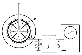
In Demonstration 1.3.1, the net charge is deduced from mechanical measurements and Coulomb's force law. Here that same charge is deduced electrically. The "ball" carrying the charge is stuck to the end of a thin plastic rod, as in Fig. 1.5.5. The objective is to measure this charge, q, without removing it from the ball.
Figure 1.5.5. When a charge q is introduced into an essentially grounded metal sphere, a charge -q is induced on its inner surface. The integral form of charge conservation, applied to the surface S, shows that i = dq/dt. The net excursion of the integrated signal is then a direct measurement of q. We know from the discussion of Gauss' law in Sec. 1.3 that this charge is the source of an electric field. In general, this field terminates on charges of opposite sign. Thus, the net charge that terminates the field originating from q is equal in magnitude and opposite in sign to q. Measurement of this "image" charge is tantamount to measuring q.
How can we design a metal electrode so that we are guaranteed that all of the lines of E originating from q will be terminated on its surface? It would seem that the electrode should essentially surround q. Thus, in the experiment shown in Fig. 1.5.5, the charge is transported to the interior of a metal sphere through a hole in its top. This sphere is grounded through a resistance R and also surrounded by a grounded shield. This resistance is made low enough so that there is essentially no electric field in the region between the spherical electrode, and the surrounding shield. As a result, there is negligible charge on the outside of the electrode and the net charge on the spherical electrode is just that inside, namely -q.
Now consider the application of (2) to the surface S shown in Fig. 1.5.5. The surface completely encloses the spherical electrode while excluding the charge q at its center. On the outside, it cuts through the wire connecting the electrode to the resistance R. Thus, the volume integral in (2) gives the net charge -q, while contributions to the surface integral only come from where S cuts through the wire. By definition, the integral of J
da over the cross-section of the wire gives the current i (amps). Thus, (2) becomes simply
This current is the result of having pushed the charge through the hole to a position where all the field lines terminated on the spherical electrode.
3 Note that if we were to introduce the charged ball without having the spherical electrode essentially grounded through the resistance R, charge conservation (again applied to the surface S) would require that the electrode retain charge neutrality. This would mean that there would be a charge q on the outside of the electrode and hence a field between the electrode and the surrounding shield. With the charge at the center and the shield concentric with the electrode, this outside field would be the same as in the absence of the electrode, namely the field of a point charge, (1.3.12).Although small, the current through the resistor results in a voltage.
The integrating circuit is introduced into the experiment in Fig. 1.5.5 so that the oscilloscope directly displays the charge. With this circuit goes a gain A such that
Then, the voltage vo to which the trace on the scope rises as the charge is inserted through the hole reflects the charge q. This measurement of q corroborates that of Demonstration 1.3.1.
In retrospect, because S and V are arbitrary in the integral laws, the experiment need not be carried out using an electrode and shield that are spherical. These could just as well have the shape of boxes.


 o E in Gauss' law is played by J,
while that of