
10.7
Skin Effect
If the surface current source driving the conducting block of Fig. 10.6.1 is a sinusoidal function of time
the current density tends to circulate through the block in the neighborhood of the surface adjacent to the source. This tendency for the sinusoidal steady state current to return to the source through the thin zone or skin region nearest to the source gives another view of magnetic diffusion.
To illustrate skin effect in specific terms we return to the one-dimensional diffusion configuration of Sec. 10.6, Fig. 10.6.1. Once again, the distributions of Hz and Jy are governed by the one-dimensional diffusion equation and Ampère's law, (10.6.1) and (10.6.2).
The diffusion equation is linear and has coefficients that are independent of time. We can expect a sinusoidal steady state response having the same frequency as the drive, (1). The solution to the diffusion equation is therefore taken as having a product form, but with the time dependence stipulated at the outset.
At a given location x, the coefficient of the exponential is a complex number specifying the magnitude and phase of the field.
Substitution of (2) into the diffusion equation, (10.6.1), shows that the complex amplitude has an x dependence governed by
where
2
j
.
Solutions to (3) are simply exp (

x). However,
is complex. If we note that
j = (1 + j)/
2, then it follows that
In terms of the skin depth
, defined by
One can also write (4) as
With C+ and C- arbitrary coefficients, solutions to (3) are therefore
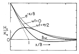
Before considering a detailed example where these coefficients are evaluated using the boundary conditions, consider the x - t dependence of the field represented by the first solution in (7). Substitution into (2) gives
making it clear that the field magnitude is an exponentially decaying function of x. Within the envelope with the decay length
shown in Fig. 10.7.1, the field propagates in the x direction. That is, points of constant phase on the field distribution have
t - x/
= constant and hence move in the x direction with the velocity
. Although the phase propagation signifies that at a given instant, the field (and current density) are positive in one region while negative in another, the propagation is difficult to discern because the decay is very rapid.
Figure 10.7.1 Magnetic diffusion wave in the sinusoidal steady state, showing envelope with decay length and instantaneous field at two different times. The point of zero phase propagates with the velocity
.
The second solution in (7) represents a similar diffusion wave, but decaying and propagating in the -x rather than the +x direction. The following illustrates how the two diffusion waves combine to satisfy boundary conditions.
Example 10.7.1. Diffusion into a Conductor of Finite Thickness
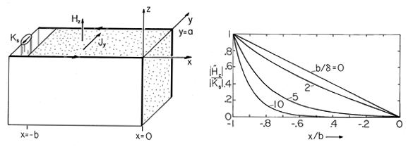
We consider once again the field distribution in a conducting material sandwiched between perfectly conducting plates, as shown in either Fig. 10.7.2 or Fig. 10.6.1. The surface current density of the drive is given by (1) and it is assumed that any transient reflecting the initial conditions has died out. How does the frequency dependence of the field distribution in the conducting block reflect the magnetic diffusion process?
Figure 10.7.2 (a) One-dimensional magnetic diffusion in the sinusoidal steady state in the same configuration as considered in Sec. 10.6. (b) Distribution of the magnitude of Hz in the conducting block of (a) as a function of the skin depth. Decreasing the skin depth is equivalent to raising the frequency. Boundary conditions on Hz are the same as in Sec. 10.6, Hz (-b, t) = Ks(t) and Hz (0, t) = 0. These are satisfied by adjusting the complex amplitude so that
It follows from (7) that the second of these is satisfied if C+ = -C-. The first condition then serves to evaluate C+ and hence C-, so that
This expression represents the superposition of fields propagating and decaying in the
x directions, respectively. Evaluated at a given location x, it is a complex number. In accordance with (2), Hz is the real part of this number multiplied by exp (j
t). The magnitude of Hz is the magnitude of (10), and is shown with the skin depth as a parameter by Fig. 10.7.2.
Consider the field distribution in two limits. First, suppose that the skin depth is very large compared to the thickness b of the conducting block. This might be the limit in which the frequency is made very low compared to the reciprocal magnetic diffusion time based on the conductor thickness.
In this limit, the arguments of the exponentials in (10) are small. Using the approximation exp (u)
1 + u, (10) becomes
Substitution of this complex amplitude into (2) gives the space-time dependence.
The field has the linear distribution expected if the current density is uniformly distributed over the length of the conductor. In this large skin depth limit, the field and current density spatial distributions are essentially the same as if the current source were time independent.
In the opposite extreme, the skin depth is short compared to the conductor length. Perhaps this is accomplished by making the frequency very high compared to the reciprocal magnetic diffusion time based on the conductor length.
Then, the first term in the denominator of (10) is large compared with the second. Division of the numerator by this first term gives
In justifying the second of these expressions, remember that x is negative throughout the region of interest. Substitution of (15) into (2) shows that in this short skin depth limit
With the origin shifted from x = 0 to x = -b, this field has the x - t dependence of the diffusion wave represented by (8). So it is that in the short skin depth limit, the distribution of the field magnitude shown in Fig. 10.7.2 has the exponential decay typical of skin effect.
The skin depth, (5), is inversely proportional to the square root of
. Thus, an order of magnitude variation in frequency or in conductivity only changes
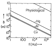
by about a factor of about 3. Even so, skin depths found under practical conditions are widely varying because these parameters have enormous ranges. In good conductors, such as copper or aluminum, Fig. 10.7.3 illustrates how
varies from about 1 cm at 60 Hz to less than 0.1 mm at l MHz. Of interest in determining magnetically induced currents in flesh is the curve for skin depth in materials having the "physiological" conductivity of about 0.2 S/m (Demonstration 7.9.1).
Figure 10.7.3 Skin depth as a function of frequency. If the frequency is high enough so that the skin depth is small compared with the dimensions of interest, then the fields external to the conductor are essentially determined using the perfect conductivity model introduced in Sec. 8.4. In Demonstration 8.6.1, the fields around a conductor above a ground plane line were derived and the associated surface current densities deduced. If these currents are in the sinusoidal steady state, we can now picture them as actually extending into the conductors a distance that is on the order of
.
Although skin effect determines the paths of current flow at radio frequencies, as the following demonstrates, it can be important even at 60 Hz.
Demonstration 10.7.1. Skin Effect
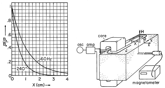
The core of magnetizable material shown in Fig. 10.7.4 passes through a slit cut from an aluminum block and through a winding that is driven at a frequency in the range of 60-240 Hz. The winding and the block of aluminum, respectively, comprise the primary and secondary of a transformer. In effect, the secondary is composed of one turn that is shorted on itself.
Figure 10.7.4 Demonstration of skin effect. Currents induced in the conducting block tend to follow paths of minimum reactance nearest to the slot. Thus, because the aluminum block is thick compared to the skin depth, the field intensity observed decreases exponentially with distance X. In the experiment, the block is 10 x 10 x 26 cm with thickness of 6 cm between the right face of the slot and the right side of the block. In aluminum at 60 Hz, = 1.1 cm, while at 240 Hz
is half of that. To avoid distortion of the field, the yoke is placed at one end of the slot.
The thickness b of the aluminum block is somewhat larger than a skin depth at 60 Hz. Therefore, currents circulating through the block around the leg of the magnetic circuit tend to follow the paths of least reactance closest to the slit. By making the length of the block and slit in the y direction large compared to b, we expect to see distributions of current density and associated magnetic field intensity at locations in the block well removed from the ends that have the x dependence found in Example 10.7.1.
In the limit where
is small compared to b, the magnitude of the expected magnetic flux density Bz (normalized to its value where X = 0) has the exponential decay with distance x of the inset to Fig. 10.7.4. The curves shown are for aluminum at frequencies of 60 Hz and 240 Hz. According to (5), increasing the frequency by a factor of 4 should decrease the skin depth by a factor of 2. Provision is made for measuring this field by having a small slit milled in the block with a large enough width to permit the insertion of a magnetometer probe oriented to measure the magnetic flux density in the z direction.
As we have seen in this and previous sections, currents induced in a conductor tend to exclude the magnetic field from some region. Conductors are commonly used as shields that isolate a region from its surroundings. Typically, the conductor is made thick compared to the skin depth based on the fields to be shielded out. However, our studies of currents induced in thin conducting shells in Secs. 10.3 and 10.4 make it clear that this can be too strict a requirement for good shielding. The thin-sheet model can now be seen to be valid if the skin depth
is large compared to the thickness
of the sheet. Yet, we found that for a cylindrical shell of radius R, provided that
R
1, a sinusoidally varying applied field would be shielded from the interior of the shell. Apparently, under certain circumstances, even a conductor that is thin compared to a skin depth can be a good shield.
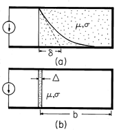
Figure 10.7.5 Perfectly conducting -shaped conductors are driven by a distributed current source at the left. The magnetic field is shielded out of the region to the right enclosed by the perfect conductors by: (a) a block of conductor that fills the region and has a thickness b that is large compared to a skin depth; and (b) a sheet conductor having a thickness
that is less than the skin depth.
To understand this seeming contradiction, consider the one-dimensional configurations shown in Fig. 10.7.5. In the first of the two, plane parallel perfectly conducting electrodes again sandwich a block of conductor in a system that is very long in a direction perpendicular to the paper. However, now the plates are shorted by a perfect conductor at the right. Thus, at very low frequencies, all of the current from the source circulates through the perfectly conducting plates, bypassing the block. As a result, the field throughout the conductor is uniform. As the frequency is raised, the electric field generated by the time-varying magnetic flux drives a current through the block much as in Example 10.7.1, with the current in the block tending to circulate through paths of least reactance near the left edge of the block. For simplicity, suppose that the skin depth
is shorter than the length of the block b, so that the decay of current density and field into the block is essentially the exponential sketched in Fig. 10.7.5a. With the frequency high enough to make the skin depth short compared to b, the field tends to be shielded from points within the block.
In the configuration of Fig. 10.7.5b, the block is replaced by a sheet having the same
and
but a thickness
that is less than a skin depth
. Is it possible that this thin sheet could suppress the field in the region to the right as well as the thick conductor?
The answer to this question depends on the location of the observer and the extent b of the region with which he or she is associated. In the conducting block, shielding is poor in the neighborhood of the left edge but rapidly improves at distances into the interior that are of the order of
or more. By contrast, the sheet conductor can be represented as a current divider. The surface current, Ks, of the source is tapped off by the sheet of conductivity per unit width G =
/h (where h is the height of the structure) connected to the inductance (assigned to unit width) L =
bh of the single-turn inductor. The current through the single-turn inductor is
This current, and the associated field, is shielded out effectively when |
LG| =
b

1. With the sheet, the shielding strategy is to make equal use of all of the volume to the right for generating an electric field in the sheet conductor. The efficiency of the shielding is improved by making
b large: The interior field is made small by making the shielded volume large.


