
13.0
Introduction
In the treatment of EQS and MQS systems, we started in Chaps. 4 and 8, respectively, by analyzing the fields produced by specified (known) sources. Then we recognized that in the presence of materials, at least some of these sources were induced by the fields themselves. Induced surface charge and surface current densities were determined by making the fields satisfy boundary conditions. In the volume of a given region, fields were composed of particular solutions to the governing quasistatic equations (the scalar and vector Poisson equations for EQS and MQS systems, respectively) and those solutions to the homogeneous equations (the scalar and vector Laplace equation, respectively) that made the total fields satisfy appropriate boundary conditions.
We now embark on a similar approach in the analysis of electrodynamic fields. Chapter 12 presented a study of the fields produced by specified sources (dipoles, line sources, and surface sources) and obeying the inhomogeneous wave equation. Just as in the case of EQS and MQS systems in Chap. 5 and the last half of Chap. 8, we shall now concentrate on solutions to the homogeneous source-free equations. These solutions then serve to obtain the fields produced by sources lying outside (maybe on the boundary) of the region within which the fields are to be found. In the region of interest, the fields generally satisfy the inhomogeneous wave equation. However in this chapter, where there are no sources in the volume of interest, they satisfy the homogeneous wave equation. It should come as no surprise that, following this systematic approach, we shall reencounter some of the previously obtained solutions.
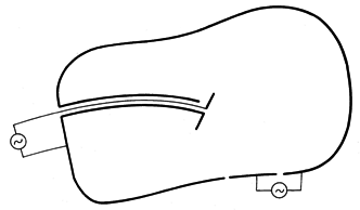
In this chapter, fields will be determined in some limited region such as the volume V of Fig. 13.0.1. The boundaries might be in part perfectly conducting in the sense that on their surfaces, E is perpendicular and the time-varying H is tangential. The surface current and charge densities implied by these conditions are not known until after the fields have been found. If there is material within the region of interest, it is perfectly insulating and of piece-wise uniform permittivity
and permeability
.
1 If the region is one of free space,


 o and
o and 

 o.
o.Sources J and
are specified throughout the volume and appear as driving terms in the inhomogeneous wave equations, (12.6.8) and (12.6.32). Thus, the H and E fields obey the inhomogeneous wave-equations.
Figure 13.0.1 Fields in a limited region are in part due to sources induced on boundaries by the fields themselves. As in earlier chapters, we might think of the solution to these equations as the sum of a part satisfying the inhomogeneous equations throughout V (particular solution), and a part satisfying the homogeneous wave equation throughout that region. In principle, the particular solution could be obtained using the superposition integral approach taken in Chap. 12. For example, if an electric dipole were introduced into a region containing a uniform medium, the particular solution would be that given in Sec. 12.2 for an electric dipole. The boundary conditions are generally not met by these fields. They are then satisfied by adding an appropriate solution of the homogeneous wave equation.
2 As pointed out in Sec. 12.7, this is essentially what is being done in satisfying boundary conditions by the method of images.
In this chapter, the source terms on the right in (1) and (2) will be set equal to zero, and so we shall be concentrating on solutions to the homogeneous wave equation. By combining the solutions of the homogeneous wave equation that satisfy boundary conditions with the source-driven fields of the preceding chapter, one can describe situations with given sources and given boundaries.
In this chapter, we shall consider the propagation of waves in some axial direction along a structure that is uniform in that direction. Such waves are used to transport energy along pairs of conductors (transmission lines), and through waveguides (metal tubes at microwave frequencies and dielectric fibers at optical frequencies). We confine ourselves to the sinusoidal steady state.
Sections 13.1-13.3 study two-dimensional modes between plane parallel conductors. This example introduces the mode expansion of electrodynamic fields that is analogous to the expansion of the EQS field of the capacitive attenuator (in Sec. 5.5) in terms of the solutions to Laplace's equation. The principal and higher order modes form a complete set for the representation of arbitrary boundary conditions. The example is a model for a strip transmission line and hence serves as an introduction to the subject of Chap. 14. The higher-order modes manifest properties much like those found in Sec. 13.4 for hollow pipe guides.
The dielectric waveguides considered in Sec. 13.5 explain the guiding properties of optical fibers that are of great practical interest. Waves are guided by a dielectric core having permittivity larger than that of the surrounding medium but possess fields extending outside this core. Such electromagnetic waves are guided because the dielectric core slows the effective velocity of the wave in the guide to the point where it can match the velocity of a wave in the surrounding region that propagates along the guide but decays in a direction perpendicular to the guide.
The fields considered in Secs. 13.1-13.3 offer the opportunity to reinforce the notions of quasistatics. Connections between the EQS and MQS fields studied in Chaps. 5 and 8, respectively, and their corresponding electrodynamic fields are made throughout Secs. 13.1-13.4.


