
13.1
Introduction to TEM Waves
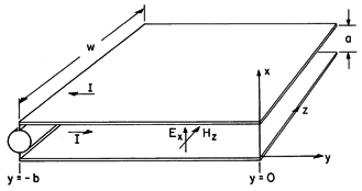
The E and H fields of transverse electromagnetic waves are directed transverse to the direction of propagation. It will be shown in Sec. 14.2 that such TEM waves propagate along structures composed of pairs of perfect conductors of arbitrary cross-section. The parallel plates shown in Fig. 13.1.1 are a special case of such a pair of conductors. The direction of propagation is along the y axis. With a source driving the conductors at the left, the conductors can be used to deliver electrical energy to a load connected between the right edges of the plates. They then function as a parallel plate transmission line.
We assume that the plates are wide in the z direction compared to the spacing, a, and that conditions imposed in the planes y = 0 and y = -b are independent of z, so that the fields are also z independent. In this section, discussion is limited to either "open" electrodes at y = 0 or "shorted" electrodes. Techniques for dealing with arbitrarily terminated transmission lines will be introduced in Chap. 14. The "open" or "shorted" terminals result in standing waves that serve to illustrate the relationship between simple electrodynamic fields and the EQS and MQS limits. These fields will be generalized in the next two sections, where we find that the TEM wave is but one of an infinite number of modes of propagation along the y axis between the plates.
Figure 13.1.1 Plane parallel plate transmission line. If the plates are open circuited at the right, as shown in Fig. 13.1.1, a voltage is applied at the left at y = -b, and the fields are EQS, the E that results is x directed. (The plates form a parallel plate capacitor.) If they are "shorted" at the right and the fields are MQS, the H that results from applying a current source at the left is z directed. (The plates form a one-turn inductor.) We are now looking for solutions to Maxwell's equations (12.0.7)-(12.0.10) that are similarly transverse to the y axis.
Fields of this form automatically satisfy the boundary conditions of zero tangential E and normal H (normal B) on the surfaces of the perfect conductors. These fields have no divergence, so the divergence laws for E and H [(12.0.7) and (12.0.10)] are automatically satisfied. Thus, the remaining laws, Ampère's law (12.0.8) and Faraday's law (12.0.9) fully describe these TEM fields. We pick out the only components of these laws that are not automatically satisfied by observing that
Ex/
t drives the x component of Ampère's law and
Hz/
t is the source term of the z component of Faraday's law.
The other components of these laws are automatically satisfied if it is assumed that the fields are independent of the transverse coordinates and thus depend only on y.
The effect of the plates is to terminate the field lines so that there are no fields in the regions outside. With Gauss' continuity condition applied to the respective plates, Ex terminates on surface charge densities of opposite sign on the respective electrodes.
These relationships are illustrated in Fig. 13.1.2a.
Figure 13.1.2 (a) Surface charge densities terminating E of TEM field between electrodes of Fig. 13.1.1. (b) Surface current densities terminating H. The magnetic field is terminated on the plates by surface current densities. With Ampère's continuity condition applied to each of the plates,
these relationships are represented in Fig. 13.1.2b.
We shall be interested primarily in the sinusoidal steady state. Between the plates, the fields are governed by differential equations having constant coefficients. We therefore assume that the field response takes the form
where
can be regarded as determined by the source that drives the system at one of the boundaries. Substitution of these solutions into (2) and (3) results in a pair of ordinary constant coefficient differential equations describing the y dependence of Ex and Hz. Without bothering to write these equations out, we know that they too will be satisfied by exponential functions of y. Thus, we proceed to look for solutions where the functions of y in (6) take the form exp (-jky y).
Once again, we have assumed a solution taking a product form. Substitution into (2) then shows that
and substitution of this expression into (3) gives the dispersion equation
For a given frequency, there are two values of ky. A linear combination of the solutions in the form of (7) is therefore
The associated electric field follows from (8) evaluated for the
waves, respectively, using ky =

.
The amplitudes of the waves, A+ and A-, are determined by the boundary conditions imposed in planes perpendicular to the y axis. The following example illustrates how the imposition of these longitudinal boundary conditions determines the fields. It also is the first of several opportunities we now use to place the EQS and MQS approximations in perspective.
Example 13.1.1. Standing Waves on a Shorted Parallel Plate Transmission Line
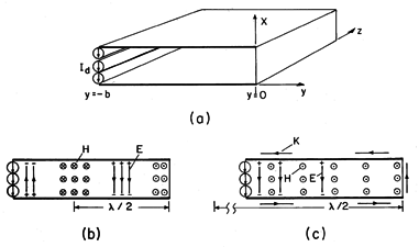
In Fig. 13.1.3a, the parallel plates are terminated at y = 0 by a perfectly conducting plate. They are driven at y = -b by a current source Id distributed over the width w. Thus, there is a surface current density Ky = Id/w
Ko imposed on the lower plate at y = -b. Further, in this example we will assume that a distribution of sources is used in the plane y = -b to make this driving surface current density uniform over that plane. In summary, the longitudinal boundary conditions are
Figure 13.1.3 (a) Shorted transmission line driven by a distributed current source. (b) Standing wave fields with E and H shown at times differing by 90 degrees. (c) MQS fields in limit where wavelength is long compared to length of system. To make Ex as given by (11) satisfy the first of these boundary conditions, we must have the amplitudes of the two traveling waves equal.
With this relation used to eliminate A+ in (10), it follows from (13) that
We have found that the fields between the plates take the form of standing waves.
Note that E and H are 90o out of temporal phase.
3 In making this and the following deductions, it is helpful to takeo as being real.
When one is at its peak, the other is zero. The distributions of E and H shown in Fig. 13.1.3b are therefore at different instants in time.
Every half-wavelength
/
from the short, E is again zero, as sketched in Fig. 13.1.3b. Beginning at a distance of a quarter-wavelength from the short, the magnetic field also exhibits nulls at half-wavelength intervals. Adjacent peaks in a given field are 180 degrees out of temporal phase.
The MQS Limit
If the driving frequency is so low that a wavelength is much longer than the length b, we have
In this limit, the fields are those of a one-turn inductor. That is, with sin (
y)

y and cos (
y)
1, (16) and (17) become
The magnetic field intensity is uniform throughout and the surface current density circulates uniformly around the one-turn loop. The electric field increases in a linear fashion from zero at the short to a maximum at the source, where the source voltage is
To make it clear that these are the fields of a one-turn solenoid (Example 8.4.4), the flux linkage
has been identified as
where L is the inductance.
The MQS Approximation
In Chap. 8, we would have been led to these same limiting fields by assuming at the outset that the displacement current, the term on the right in (2), is negligible. Then, this one-dimensional form of Ampère's law and (1) requires that
If we now use this finding in Faraday's law, (3), integration on y and use of the boundary condition of (12) gives the same result for E as found taking the low-frequency limit, (20).
In the previous example, the longitudinal boundary conditions (conditions imposed at planes of constant y) could be satisfied exactly using the TEM mode alone. The short at the right and the distributed current source at the left each imposed a condition that was, like the TEM fields, independent of the transverse coordinates. In almost all practical situations, longitudinal boundary conditions which are independent of the transverse coordinates (used to describe transmission lines) are approximate. The open circuit termination at y = 0, shown in Fig. 13.1.4, is a case in point, as is the source which in this case is not distributed in the x direction.
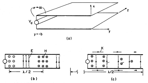
Figure 13.1.4 (a) Open circuit transmission line driven by voltage source. (b) E and H at times that differ by 90 degrees. (c) EQS fields in limit where wavelength is long compared to b. If a longitudinal boundary condition is independent of z, the fields are, in principle, still two dimensional. Between the plates, we can therefore think of satisfying the longitudinal boundary conditions using a superposition of the modes to be developed in the next section. These consist of not only the TEM mode considered here, but of modes having an x dependence. A detailed evaluation of the coefficients specifying the amplitudes of the higher-order modes brought in by the transverse dependence of a longitudinal boundary condition is illustrated in Sec. 13.3. There we shall find that at low frequencies, where these higher-order modes are governed by Laplace's equation, they contribute to the fields only in the vicinity of the longitudinal boundaries. As the frequency is raised beyond their respective cutoff frequencies, the higher-order modes begin to propagate along the y axis and so have an influence far from the longitudinal boundaries.
Here, where we wish to restrict ourselves to situations that are well described by the TEM modes, we restrict the frequency range of interest to well below the lowest cutoff frequency of the lowest of the higher-order modes.
Given this condition, "end effects" are restricted to the neighborhood of a longitudinal boundary. Approximate boundary conditions then determine the distribution of the TEM fields, which dominate over most of the length. In the open circuit example of Fig. 13.1.4a, application of the integral charge conservation law to a volume enclosing the end of one of the plates, as illustrated in Fig. 13.1.5, shows that Ky must be essentially zero at y = 0. For the TEM fields, this implies the boundary condition4
4In the region outside, the fields are not confined by the plates. As a result, there is actually some radiation from the open end of the line, and this too is not represented by (24). This effect is small if the plate spacing is small compared to a wavelength.
Figure 13.1.5 The surface current density, and hence, Hz go to zero in the vicinity of the open end. At the left end, the vertical segments of perfect conductor joining the voltage source to the parallel plates require that Ex be zero over these segments. We shall show later that the higher-order modes do not contribute to the line integral of E between the plates. Thus, in so far as the TEM fields are concerned, the requirement is that
Example 13.1.2. Standing Waves on an Open-Circuit Parallel Plate Transmission Line
Consider the parallel plates "open" at y = 0 and driven by a voltage source at y = -b. Boundary conditions are then
Evaluation of the coefficients in (10) and (11) so that the boundary conditions in (26) are satisfied gives
It follows that the TEM fields between the plates, (10) and (11), are
These distributions of H and E are shown in Fig. 13.1.4 at times that differ by 90 degrees. The standing wave is similar to that described in the previous example, except that it is now E rather than H that peaks at the open end.
The EQS Limit
In the low frequency limit, where the wavelength is much longer than the length of the plates so that
b
1, the fields given by (28) and (29) become
At low frequencies, the fields are those of a capacitor. The electric field is uniform and simply equal to the applied voltage divided by the spacing. The magnetic field varies in a linear fashion from zero at the open end to its peak value at the voltage source. Evaluation of -Hz at z = -b gives the surface current density, and hence the current i, provided by the voltage source.
Note that this expression implies that
so that the limiting behavior is indeed that of a plane parallel capacitor.
EQS Approximation
How would the quasistatic fields be predicted in terms of the TEM fields? If quasistatic, we expect the system to be EQS. Thus, the magnetic induction is negligible, so that the right-hand side of (3) is approximated as being equal to zero.
It follows from integration of this expression and using the boundary condition of (26b) that the quasistatic E is
In turn, this result provides the displacement current density in Ampère's law, the right-hand side of (2).
The right-hand side of this expression is independent of y. Thus, integration with respect to y, with the "constant" of integration evaluated using the boundary condition of (26a), gives
For the sinusoidal voltage drive assumed at the outset in the description of the TEM waves, this expression is consistent with that found in taking the quasistatic limit, (30).
Demonstration 13.1.1. Visualization of Standing Waves
A demonstration of the fields described by the two previous examples is shown in Fig. 13.1.6. A pair of sheet metal electrodes are driven at the left by an oscillator. A fluorescent lamp placed between the electrodes is used to show the distribution of the rms electric field intensity.
Figure 13.1.6 (a) Plane parallel metal plates 1.75 m long are driven at the left end by a 200 MHz source. Light, and hence time average of E2, with plates (b) terminated by short and (c) terminated by an open circuit. The gas in the tube is ionized by the oscillating electric field. Through the field-induced acceleration of electrons in this gas, a sufficient velocity is reached so that collisions result in ionization and an associated optical radiation. What is seen is a time average response to an electric field that is oscillating far more rapidly than can be followed by the eye.
Because the light is proportional to the magnitude of the electric field, the observed 0.75 m distance between nulls is a half-wavelength. It can be inferred that the generator frequency is f = c/
= 3 x 10⁸/1.5 = 200 MHz. Thus, the frequency is typical of the lower VHF television channels.
With the right end of the line shorted, the section of the lamp near that end gives evidence that the electric field there is indeed as would be expected from Fig. 13.1.3b, where it is zero at the short. Similarly, with the right end open, there is a peak in the light indicating that the electric field near that end is maximum. This is consistent with the picture given in Fig. 13.1.4b. In going from an open to a shorted condition, the positions of peak light intensity, and hence of peak electric field intensity, are shifted by
/4.


